Dental implant

a technology of dental implants and implants, applied in the field of dental implants, can solve the problems of loose implants, loss of bone, weakened bond between the fixture and the maxilla or mandible,

Inactive Publication Date: 2010-05-13
CAGENIX TECH
View PDF14 Cites 52 Cited by
  • Summary
  • Abstract
  • Description
  • Claims
  • Application Information

AI Technical Summary

Problems solved by technology

There are several common problems with such two piece dental implants.
First, the bone into which they are inserted often does not bond (e.g. integrate) well with the implant, or, if bonded, degrades causing the implant to loosen over time.
Microgaps between the fixture and the abutment are one cause of this loss of bone.
By cultivating oral bacteria so close to the fixture / bone junction itself, the gingiva may become irritated or infected, and the bond between the fixture and the maxilla or mandible weakened.
Loosening may also be caused by the poor distribution of forces from the implant to the maxilla or mandible.
If the load is concentrated on a particular portion of the maxilla or mandible, this stress concentration may cause the bond between fixture and maxilla or mandible to weaken.
Stress concentrations are typically caused by improper fixture design or positioning, or a fixture that is not shaped to distribute the tooth load relatively evenly.
When multiple teeth are lost, it compounds the mentioned problems.
This remodeling is the main cause for loss of bone and tissue contours and implant stability.
Another problem often encountered with implants is the failure of the crown that is attached to the abutment.
Large loads placed on the crown when chewing cause the crown to fatigue and ultimately to fracture or fail.
These large loads can also weaken the cement that bonds the crown to the abutment if the crown-to-abutment joint design unduly concentrates the load.

Method used


Image

  • Dental implant
  • Dental implant
  • Dental implant

Examples


Embodiment Construction

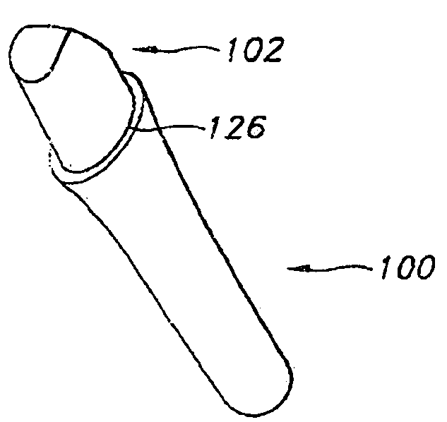
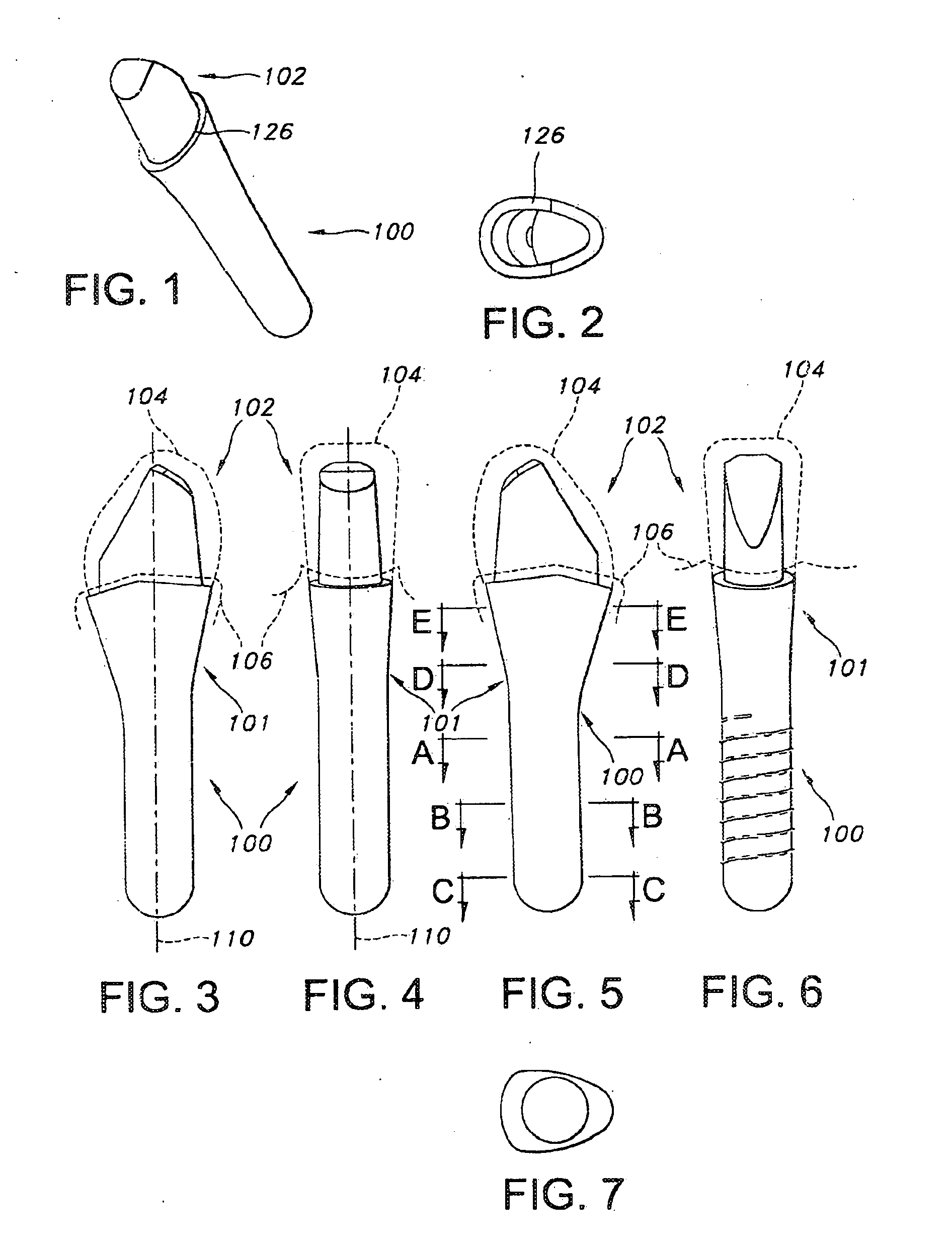
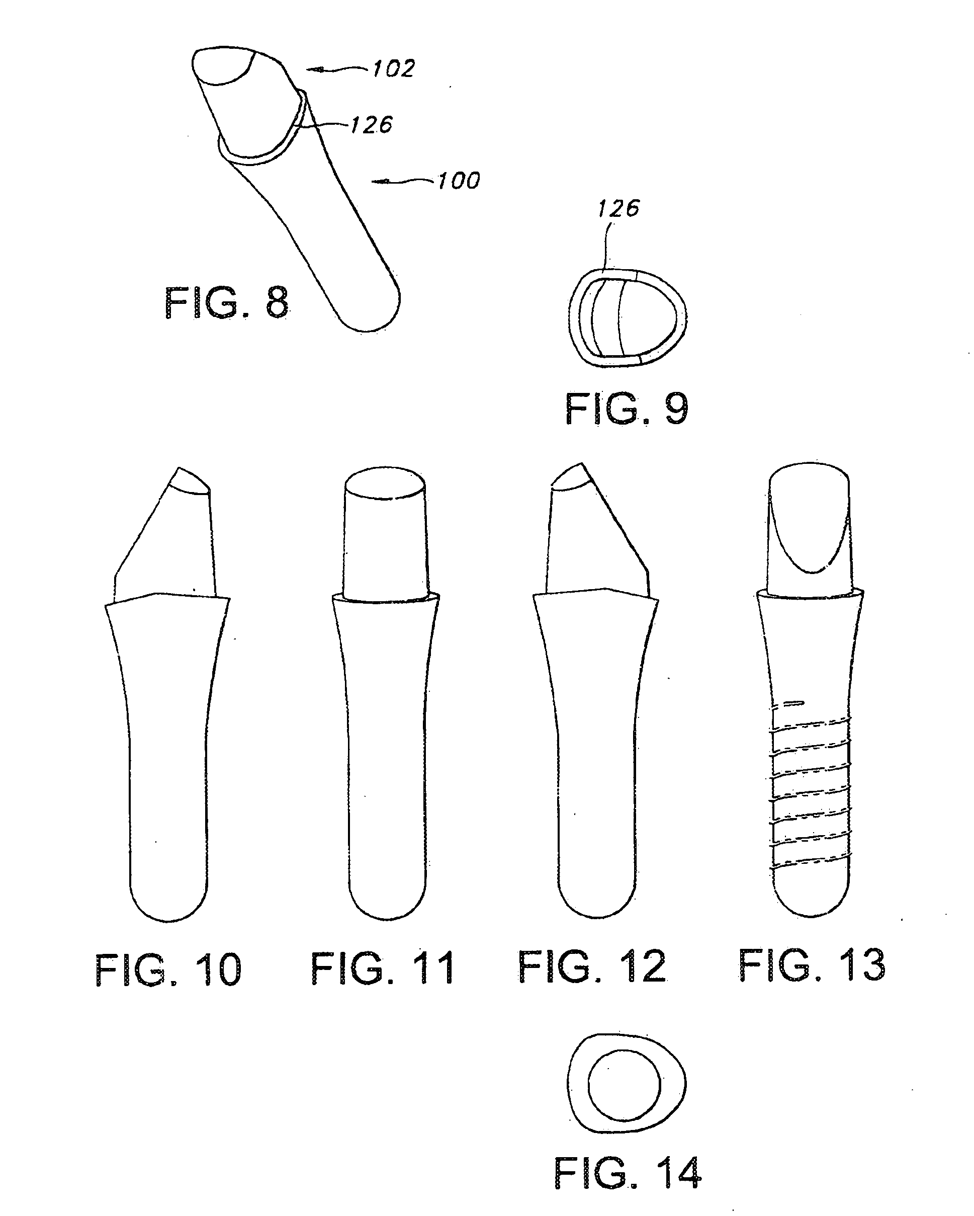
[0049]In the discussion below, the applicants describe a dental implant that is inserted into prepared holes in a mandible or maxilla. To describe several features of the implant, the Applicants use several terms that are here defined or described.

[0050]“Up” used herein with reference to teeth, implants, fixtures, or abutments, refers to the direction generally parallel to the longitudinal axis of the implant or tooth and extending away from the bone in which it is intended to be implanted (i.e. away from the root and toward the crown).

[0051]“Down” is the direction opposite to “up” (i.e. away from the crown and toward the root).

[0052]A “side”, as used with reference to teeth, implants, fixtures, or abutments, refers to the portions of the tooth or implant facing the adjacent teeth or implants when the tooth, implant, fixture, or abutment is embedded in the mandible or maxilla. The side surfaces of teeth or implants directly face the adjacent teeth or implants.

[0053]A “side” can be e...


PUM


Abstract

An oral implant for mounting in a patient's maxilla or mandible is provided that includes an abutment and a fixture. The implants may be arranged in a system including two or more adjacent implants disposed in predetermined locations and bearing a predetermined locational relationship to each other.

Description

FIELD OF THE INVENTION[0001]This invention relates to dental implants.BACKGROUND OF THE INVENTION[0002]Dental implants are used as replacements for missing teeth. Implants are typically in the form of a fixture that is coupled to an abutment. The fixture portion of a dental implant is that portion which extends into the maxilla or mandible, where it is anchored in a bone in the maxilla or mandible. The fixture typically includes a top portion that extends out of the maxilla or mandible and provides an anchoring point for an abutment. The abutment portion of a dental implant is the portion that is fixed to the fixture and extends above the gingiva. It has an upper surface that is configured to receive and support a crown.[0003]There are several common problems with such two piece dental implants. First, the bone into which they are inserted often does not bond (e.g. integrate) well with the implant, or, if bonded, degrades causing the implant to loosen over time.[0004]Microgaps betwe...

Claims


Application Information

Patent Timeline
Patent Type & Authority Applications(United States)
IPC IPC(8): A61C8/00
CPCA61C8/006A61C8/0066A61C8/0077A61C8/0075A61C8/0068
Inventor SCHULTER, CARL W.DIANGELO, DENIS J.SULLIVAN, III, CHARLES S.SCHULTER, ANDREW J.
Owner CAGENIX TECH
Why Eureka
Try Eureka