Method for anchoring autologous or artificial tendon grafts in bone
What is AI technical title?
AI technical title is built by PatSnap AI team. It summarizes the technical point description of the patent document.
a technology of autologous or artificial tendon grafts and bone, applied in the field of surgical systems, can solve the problems of cruciate ligaments, difficult to harvest tendon, postoperative complications, etc., and achieve the effect of strong pressure fi
Inactive Publication Date: 2010-05-13
DEPUY MITEK INC
View PDF99 Cites 5 Cited by
Summary
Abstract
Description
Claims
Application Information
AI Technical Summary
This helps you quickly interpret patents by identifying the three key elements:
Problems solved by technology
Method used
Benefits of technology
Benefits of technology
[0015]According to one aspect of the invention, the stabilizing element has a threaded outer surface that can be securely turned into the bone. In addition, the stabilizing element can have an inner bore that is smaller than the outer diameter of the insertion element, such that placement of the latter into the former causes the stabilizing element to deformably expand or otherwise obtain a still stronger pressure fit with the bone hole.
[0016]In another aspect, the invention provides a stabilizing element that has a flanged head that rests on the surface of the bone, outside of the bone hole, and that prevents the element from entering the bone hole beyond a certain point.
[0017]In further aspects of the invention, the insertion and stabilizing elements comprise bio-compatible materials. These avoid adverse biological reactions to the elements, as well as the need for a second surgical procedure to remove the elements.
[0018]A related aspect of the invention comprises a system comprising two or more anchoring assemblies as described above. Such a system can be used with one or more natural or artificial crafts to repair or strengthen a skeletal bone or joint. In ACL repair, for example, one stabilizing element: can be placed at one end of a bone hole drilled into the femur, and the other stabilizing element can be placed in an aligned tunnel drilled into the tibia. The first and second insertion elements can then be joined by the graft and inserted into their respective stabilizing elements. The stabilization element placed in the femur can be of the type having a threaded outer surface, while that emplaced in the tibia can be of the type having a flanged head. Such a configuration exploits the strong cancellous matter in the femur, which is well adapted to holding screw threads, and relies on the surface of the tibia to ensure a hold there.
[0022]Methods and apparatus of the instant invention overcome limitations of prior art systems for affixing grafts to bone. The two-piece apertured design enables construction of an anchor assembly to attach autologous or artificial tendon grafts securely within bone without the use of metal, and without placing the high loads on sutures that are associated with sewing or tying grafts directly to bone.
Problems solved by technology
Athletes, for example, often suffer tears or other injuries to the anterior cruciate ligament, one of the ligaments connecting the femur.
The ACL, which limits hyperextension of the knee and prevents the backward sliding of the femur on the tibial plateau, may be injured when the knee is twisted beyond the normal range of motion, e.g., when the knee is twisted while bending and weaving during skiing and other sports activities.
Drawbacks associated with the use of the patellar tendon-include difficulties in harvesting the tendon and postoperative complications.
Although semitendinosus tendons are increasingly used in ACL repair, they are difficult to attach to bone, due in part to the absence of associated bone plugs.
Drawbacks associated with this method include stretching or failure of the suture, which may be subjected to tensile forces ranging from 30-50 pounds.
Although such metal screws demonstrate stable fixation and good tensile strength, they have, a number of drawbacks.
These include distortion of post-operative radiological studies, an allergic or rejection reaction resulting from metal sensitivity associated with permanently implanted metal screws, and the potential need for additional operations for removal or replacement.
A drawback of that anchor is that it must be lodged in the cortical layer near the surface of the femur and therefore necessitates the use of long tendon segments.
Method used
Image
Click on the blue label to locate the original text in one second.
Reading with bidirectional positioning of images and text.
Examples
Embodiment Construction
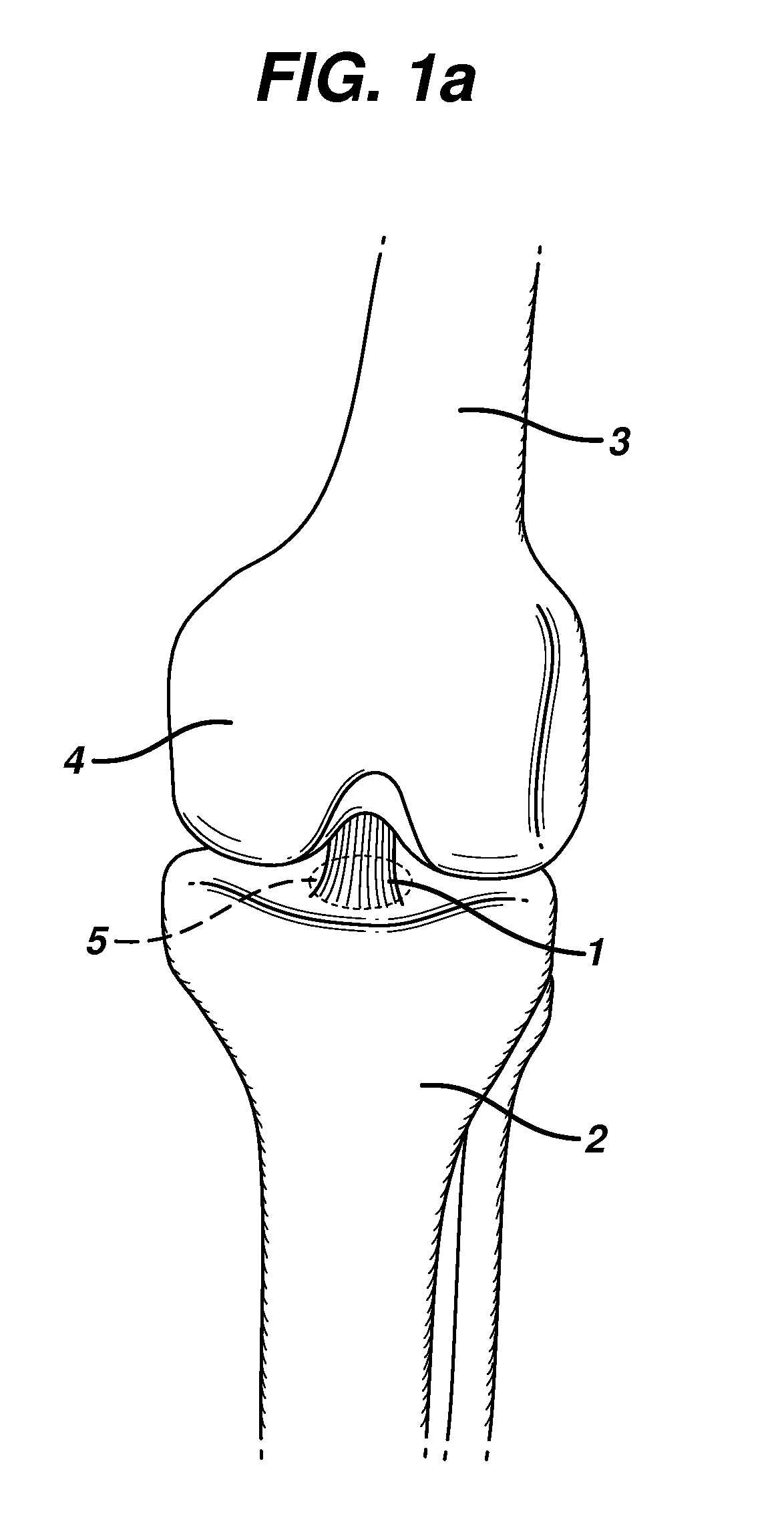
[0041]FIG. 1a depicts a partially torn ligament of the knee, e.g., the anterior cruciate ligament (ACL) 1. In the illustration, the ACL is attached to a depression in the anterior intercondylar area (not shown) on the surface of the tibial plateau 5. This tibial attachment lies in front of the anterior intercondylar tubercle and is blended with the anterior extremity of the lateral meniscus (not shown). It passes upward, backward, and laterally to be fixed into the posterior part of the medial surface of the lateral condyle (not shown) of the femur 3. The tibia 2 and the patella 4 are also shown.
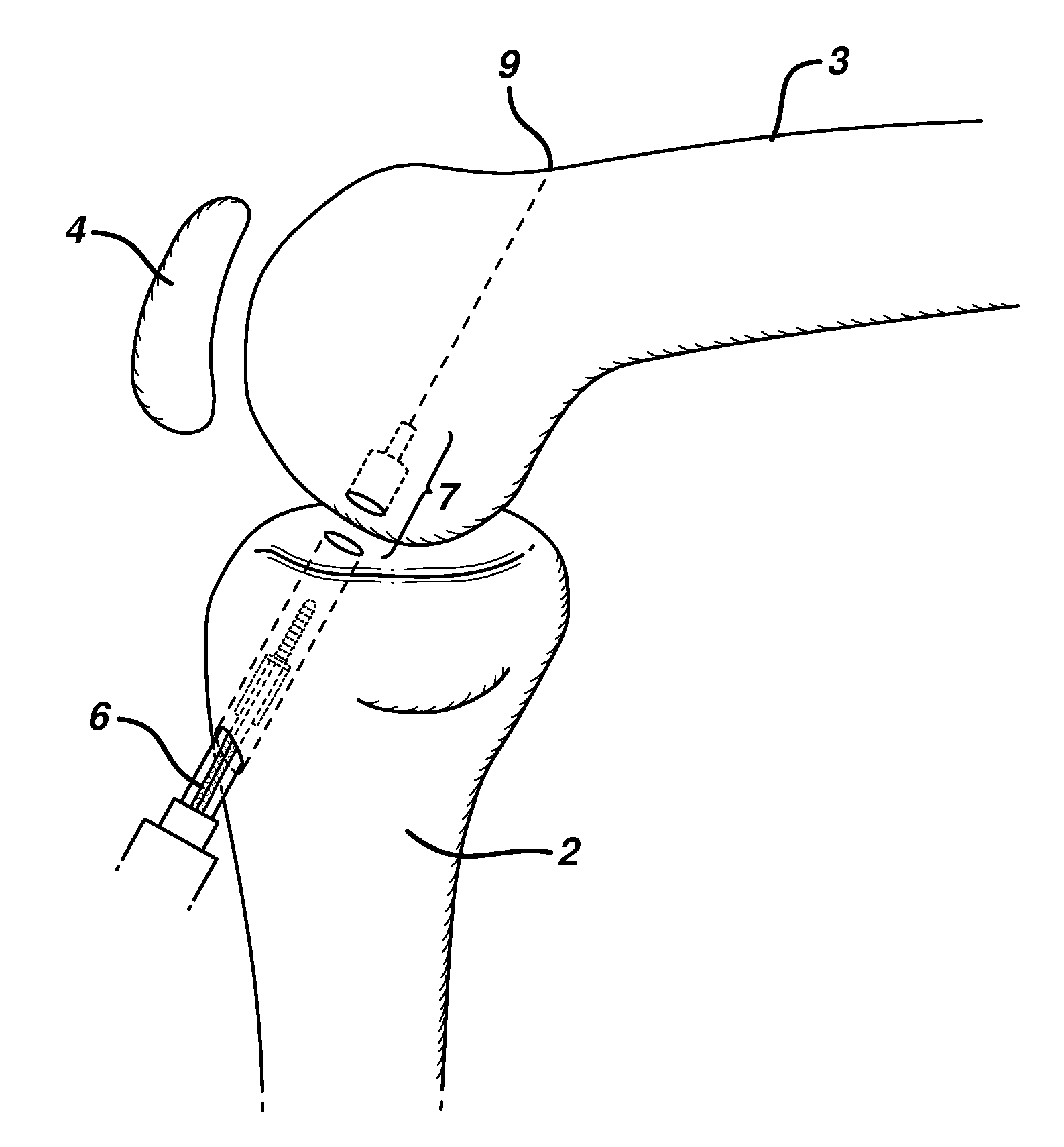
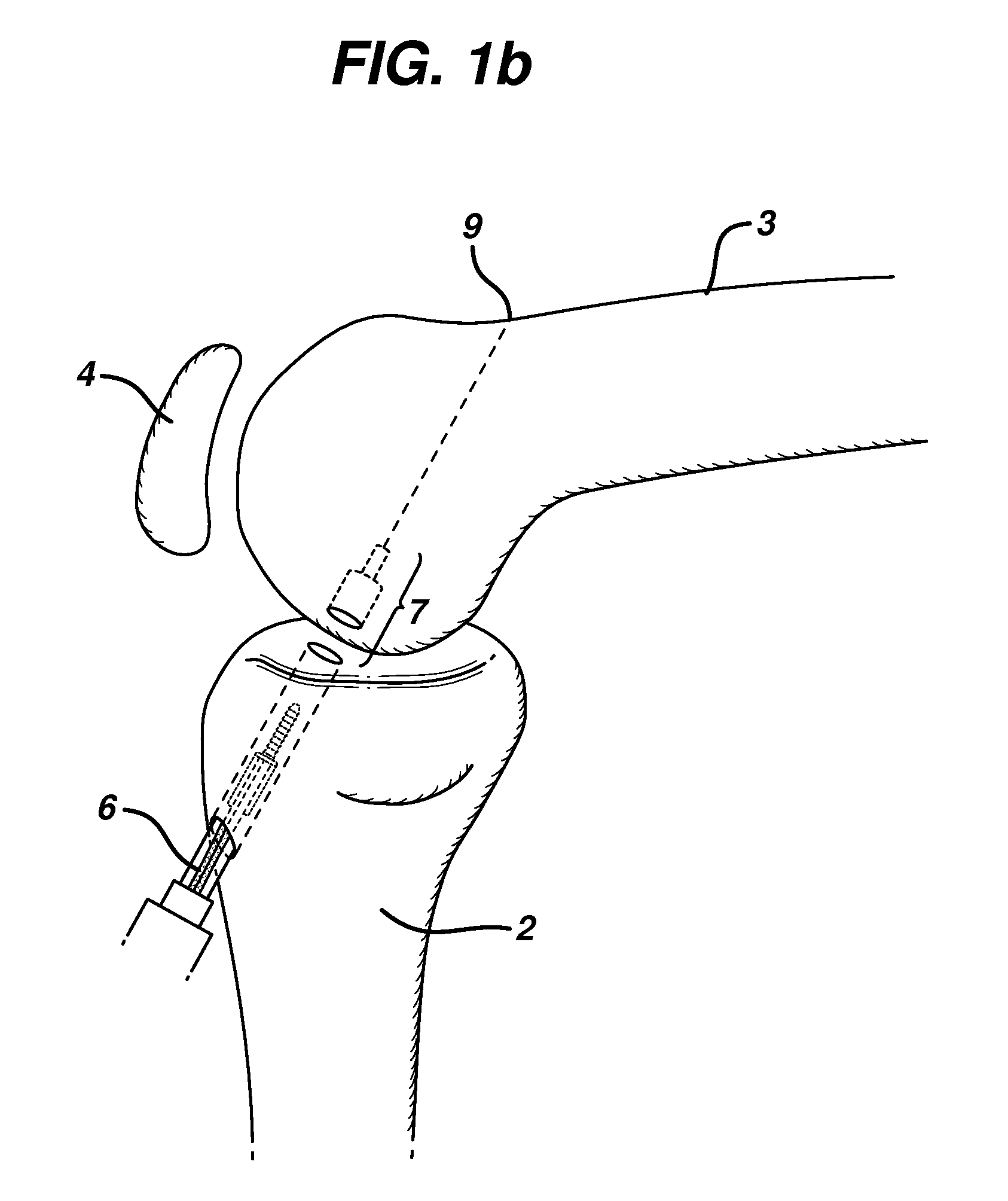
[0042]FIG. 1b depicts a method for creating a stepped tunnel 7 through the tibia 2 and partially through the femur 3 for insertion of an anchor assembly of the invention. In the illustration, a drill 6 is used by the surgeon to drill a tunnel beginning at the anterior surface of the tibia 2 and ending within the cancellous region of the femur 3. The drill tunnel 7 preferably will enter the f...
PUM
Abstract
An anchor assembly for autologous or artificial tendon grafts comprises an insertion element and a stabilizing element. The insertion element has a stem and a head containing an aperture large enough to receive a graft. The stabilizing element is adapted to be embedded in bone, and comprises a sleeve with a cavity arranged to receive and hold the insertion element stem. In use, the stabilizing element is affixed in the bone, and the stem of the insertion element is placed therein. A tendon graft may be secured to the insertion element either before or after its placement in the stabilizing element. Two such anchors may be linked with one or multiple grafts, in either a two-ply or four-ply arrangement.
Description
CROSS-REFERENCE TO RELATED APPLICATIONS[0001]This application is a divisional application of U.S. patent application Ser. No. 10 / 623,212 filed on Jul. 18, 2003, which is a divisional application of U.S. patent application Ser. No. 08 / 976,257 filed Nov. 21, 1997 (now U.S. Pat. No. 6,616,694), which claims priority to and is a continuation-in-part of U.S. patent application Ser. No. 08 / 887,580, filed Jul. 3, 1997 now abandoned, and of U.S. patent application Ser. No. 08 / 754,566, filed Nov. 21, 1996 now abandoned, the contents of which are incorporated herein by reference in their entireties.BACKGROUND OF THE INVENTION[0002]This invention pertains to surgical systems and, more particularly, apparatus and methods for attaching autologous or artificial tendon grafts to bone. The invention has application in, for example, repair of the anterior cruciate ligament (ACL) of the knee. It may also be used, for example, for repair of other ligaments, such as of the elbow or ankle[0003]It is not...
Claims
Application Information
Patent Timeline
Application Date:The date an application was filed.
Publication Date:The date a patent or application was officially published.
First Publication Date:The earliest publication date of a patent with the same application number.
Issue Date:Publication date of the patent grant document.
PCT Entry Date:The Entry date of PCT National Phase.
Estimated Expiry Date:The statutory expiry date of a patent right according to the Patent Law, and it is the longest term of protection that the patent right can achieve without the termination of the patent right due to other reasons(Term extension factor has been taken into account ).
Invalid Date:Actual expiry date is based on effective date or publication date of legal transaction data of invalid patent.
Patent Type & AuthorityApplications(United States)

