
Apparatus and method for hot bonding metal plates

a technology of metal plate and apparatus, which is applied in the direction of soldering apparatus, manufacturing tools,auxillary welding devices, etc., can solve the problems of difficult to bond metal plates with welding methods, low pressure applied to bonding surfaces, and rare use of welding methods, etc., to achieve strong bonding pressure, strong clamping force, and restricted movement of two metal plates

Active Publication Date: 2010-07-06
SUNG WOO HITECH +1
View PDF9 Cites 9 Cited by
  • Summary
  • Abstract
  • Description
  • Claims
  • Application Information

AI Technical Summary

Benefits of technology

This approach enhances bonding force, eliminates the need for additional processes, and ensures strong, efficient bonding of metal plates without pushing material in the width direction, improving productivity and maintaining pure metal contact.

Problems solved by technology

However, if the metal plates are thick or materials of the metal plates are different from each other, it is difficult to bond the metal plates with the welding method.
Thus, a welding method is rarely used in the hot rolling process.
However, if the metal plates are clamped by the triangular-prism-shaped protrusion portion, the pressure applied to the bonding surfaces may be low and flaws may occur at the metal plates.
However, an additional process for forming the protrusions and depressions may be needed and a sufficient pressure for bonding the metal plates may not be obtained since the protrusions and depressions are formed as the slanted shape.
However, since the metal plates are bonded just by the cutting and clamping force, the bonding pressure that is applied to the bonding surface in the normal direction of the bonding surface may be weakened.
However, many problems may occur such as that a preceding process for removing the oxidation film coated on the bonding surfaces of the metal plates may be performed and the additional trimming process may be performed since the metal is pushed out in the width direction and the width of the metal plates are widened.

Method used


Image

  • Apparatus and method for hot bonding metal plates
  • Apparatus and method for hot bonding metal plates
  • Apparatus and method for hot bonding metal plates

Examples


Embodiment Construction

[0053]An exemplary apparatus for hot bonding metal plates according to an embodiment of the present invention will hereinafter be described in detail with reference to the accompanying drawings.

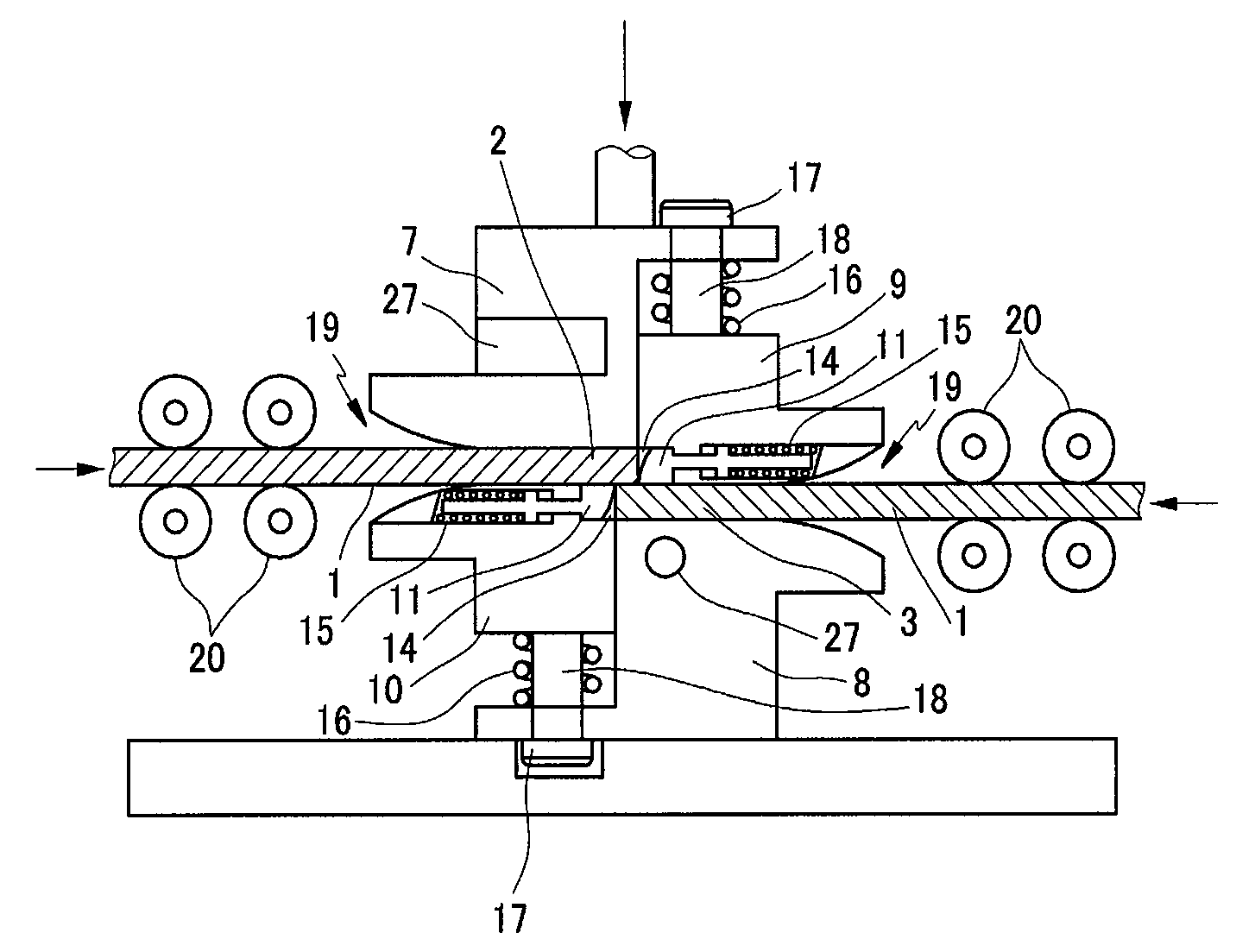
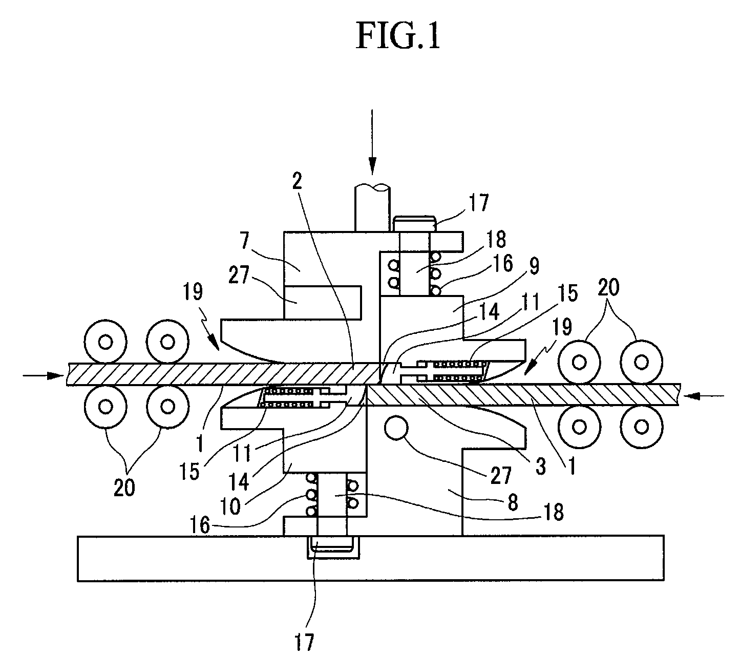
[0054]FIG. 1 shows a cross-sectional view of a bonding mold according to an exemplary embodiment of the present invention.

[0055]As shown in FIG. 1, metal plates are overlapped by an upper bonding mold 7 and a lower bonding mold 8, and a compression load is vertically applied to the overlapped surfaces 5 according to the present invention. In this case, an oxidation film of the metal plates is shaved by shaving molds 11 mounted on front portions of clamps and simultaneously the overlapped surfaces 5 of the metal plates 1 are bonded.

[0056]A bonding force in a case of using a conventional cutting blade may be stronger than the bonding force in the case of using the upper and lower bonding molds 7 and 8. However, many problems may occur such that an oxidation film coated on the overlapped surface...


PUM

PropertyMeasurementUnit
pressureaaaaaaaaaa
heightaaaaaaaaaa
thicknessaaaaaaaaaa

Abstract

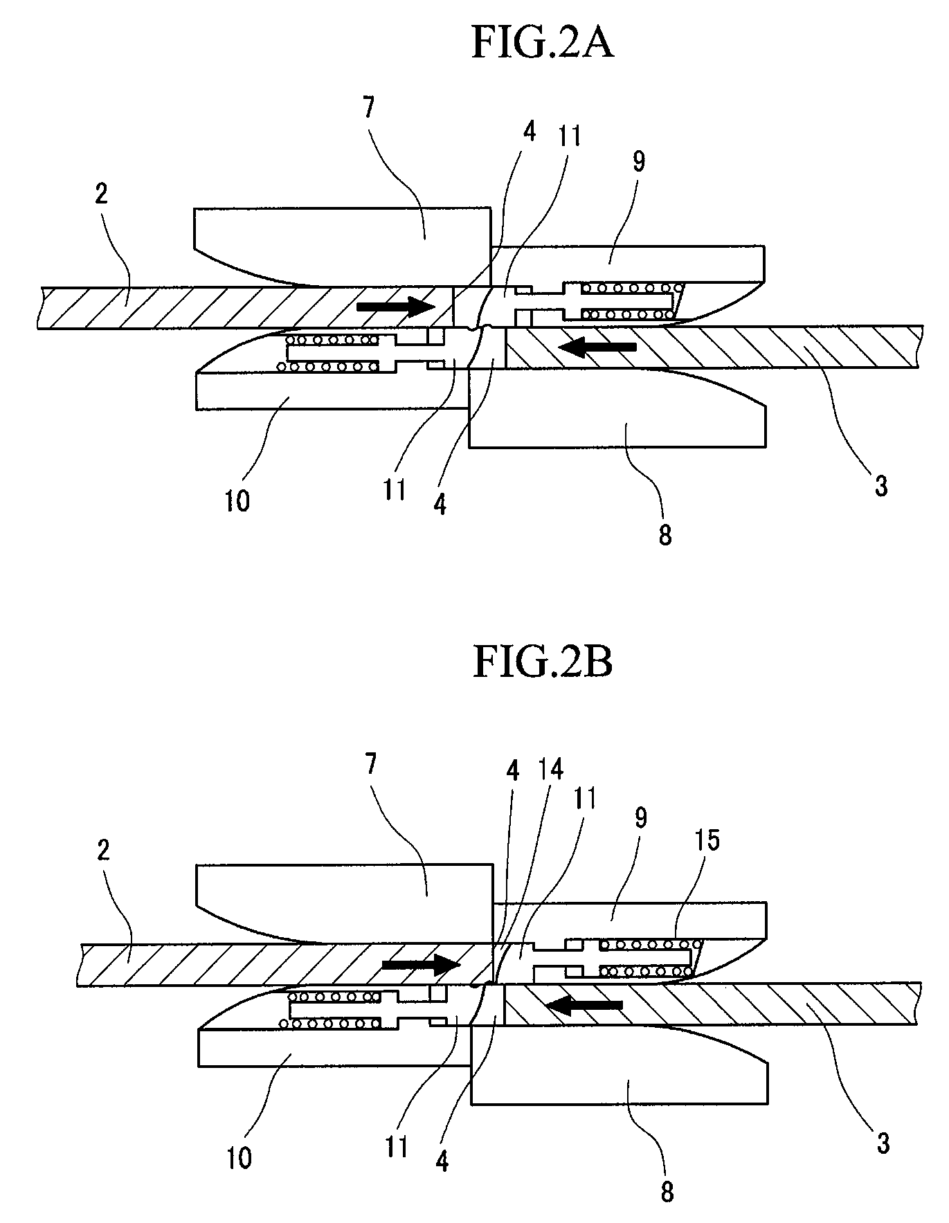
The present invention relates to an apparatus and a method for hot bonding metal plates having advantages that removing an oxidation film of the metal plates and bonding the metal plates are simultaneously accomplished and a bonding force between the metal plates is enhanced by applying a strong bonding pressure to the metal plates. The present invention has advantages that overlapped metal plates are compressed vertically and a shaving blade is formed at a shaving mold. Therefore, as the metal plates move, an oxidation film coated on the overlapped surfaces of the metal plates is removed. In addition, a home is formed at the shaving mold so that excess metal together with an oxidation film coated on front portions of the metal plates are removed and simultaneously the metal plates are bonded with a strong pressure.

Description

BACKGROUND OF THE INVENTION[0001](a) Field of the Invention[0002]The present invention relates to an apparatus and a method for hot bonding metal plates. More particularly, the present invention relates to an apparatus and a method for hot bonding metal plates having advantages that removing an oxidation film of the metal plates and bonding the metal plates are simultaneously accomplished and a bonding force between the metal plates is enhanced by applying a strong bonding pressure to the metal plates.[0003](b) Description of the Related Art[0004]Generally, a welding method is well known as the method for bonding two metal plates. However, if the metal plates are thick or materials of the metal plates are different from each other, it is difficult to bond the metal plates with the welding method. Especially, in a hot rolling process, thick moving metal plates need to be rapidly bonded so as to continuously roll the metal plates. Thus, a welding method is rarely used in the hot rolli...

Claims


Application Information

Patent Timeline
Patent Type & Authority Patents(United States)
IPC IPC(8): B23K37/00B23K20/02
CPCB23K20/023B23K20/028B23K20/24B23K2201/18B23K2101/18
Inventor JIN, IN TAI
Owner SUNG WOO HITECH
Learn More