Passive and Active Wireless Building Management System and Method

a wireless and building management technology, applied in data switching networks, instruments, analogue processes for specific applications, etc., can solve the problems of difficult to update the building model in a comprehensive and reliable manner, the building model is often somewhat obsolete, and the maintenance of the building model becomes more difficult and time-consuming

Active Publication Date: 2010-05-13
SIEMENS CORP +1
View PDF13 Cites 28 Cited by
  • Summary
  • Abstract
  • Description
  • Claims
  • Application Information

AI Technical Summary

Problems solved by technology

Historically, maintenance of the building model becomes more difficult and time-consuming as the building process progresses.
Because the actual construction involves several subcontractors, each with several employees, it is difficult to update the building model in a comprehensive and reliable manner.
As a result, the building model is often somewhat obsolete and has limited utility and reliability once the building has been constructed and is in use.
As a result, the operation of the systems in the normal activities of a building typically occurs without the benefit of an accurate and granular building model.
Nevertheless, because accurate building models for completed and occupied buildings are not readily attainable, optimization is typically attempted through trial and error.

Method used


Image

  • Passive and Active Wireless Building Management System and Method
  • Passive and Active Wireless Building Management System and Method
  • Passive and Active Wireless Building Management System and Method

Examples


Embodiment Construction

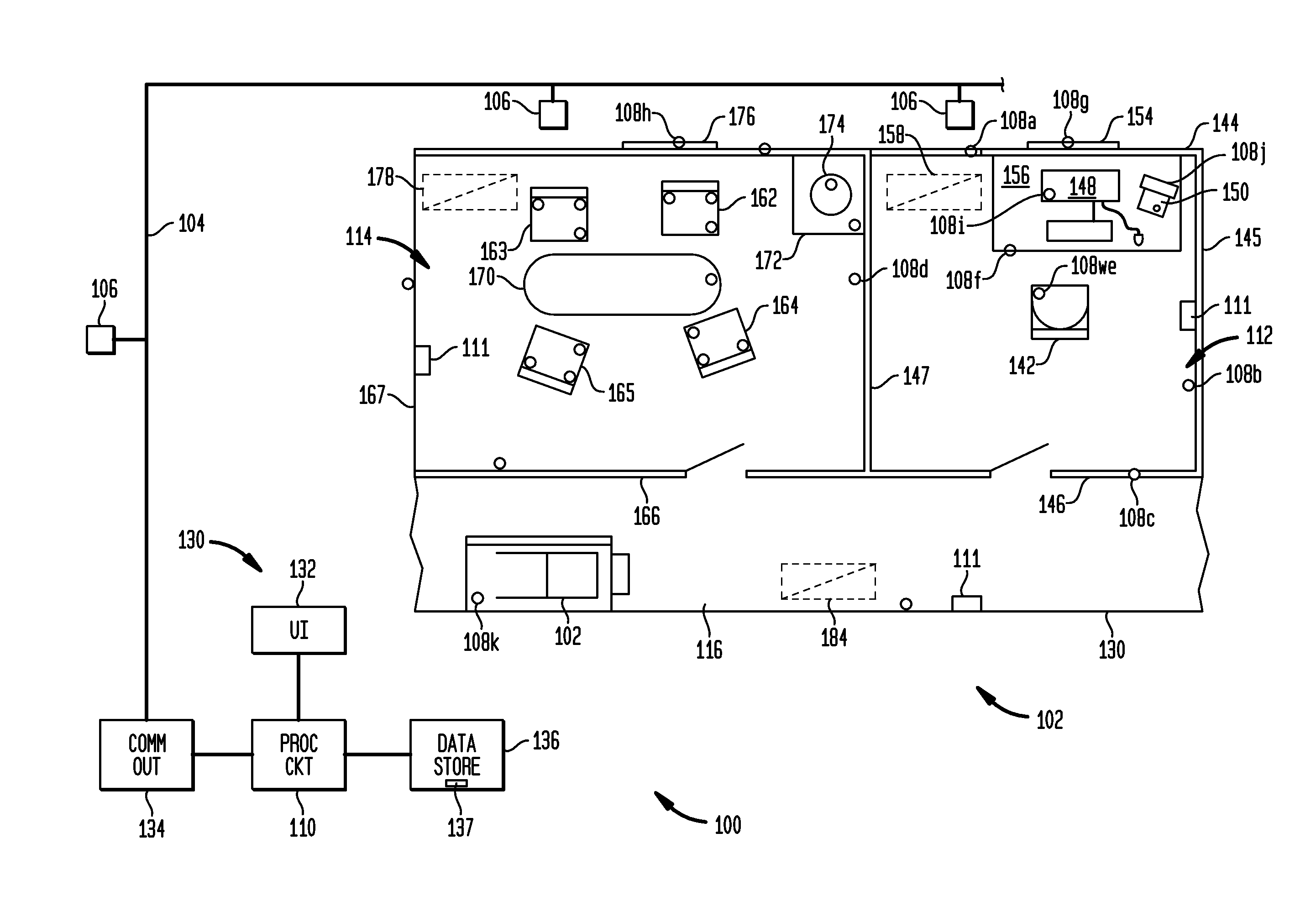
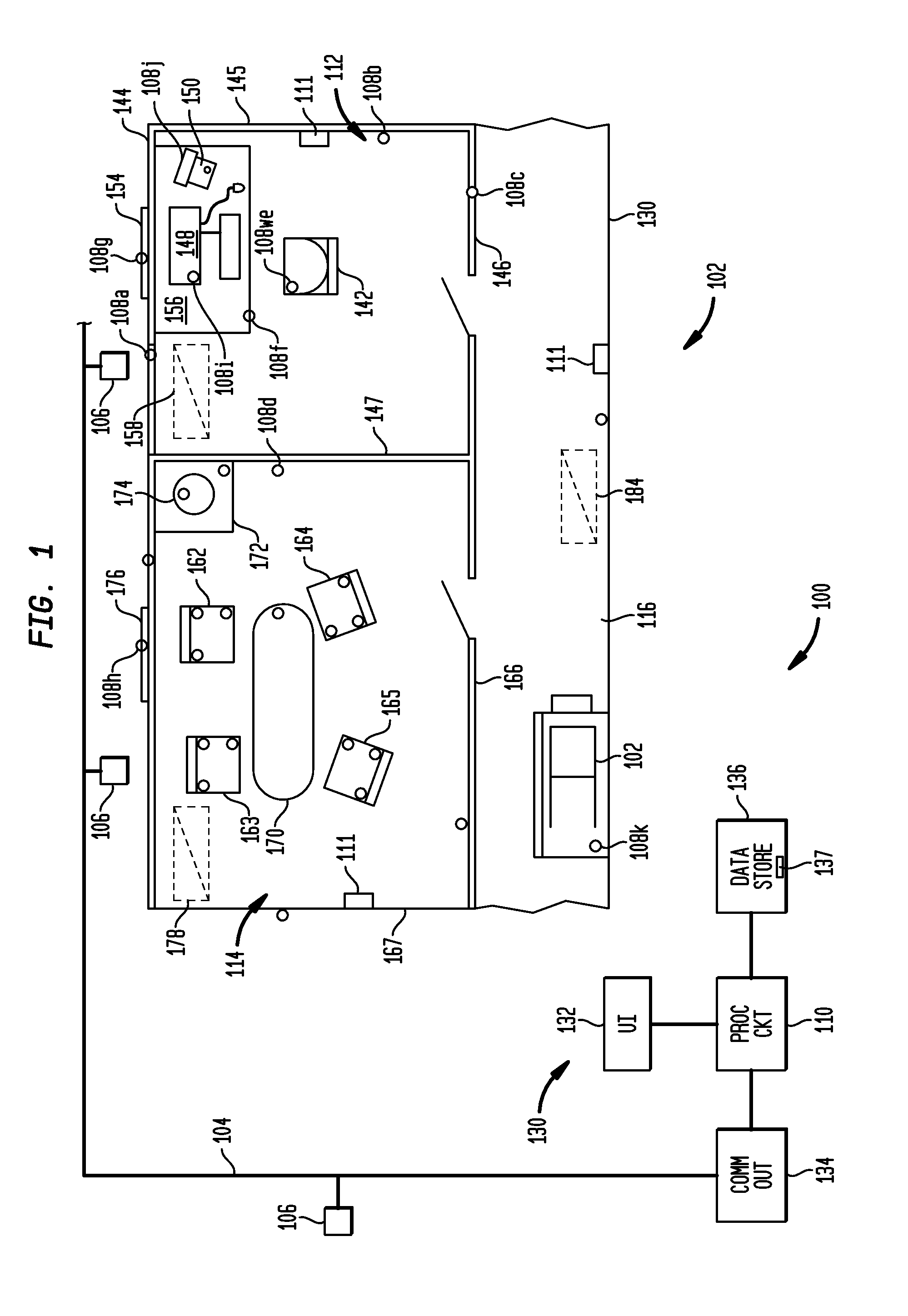
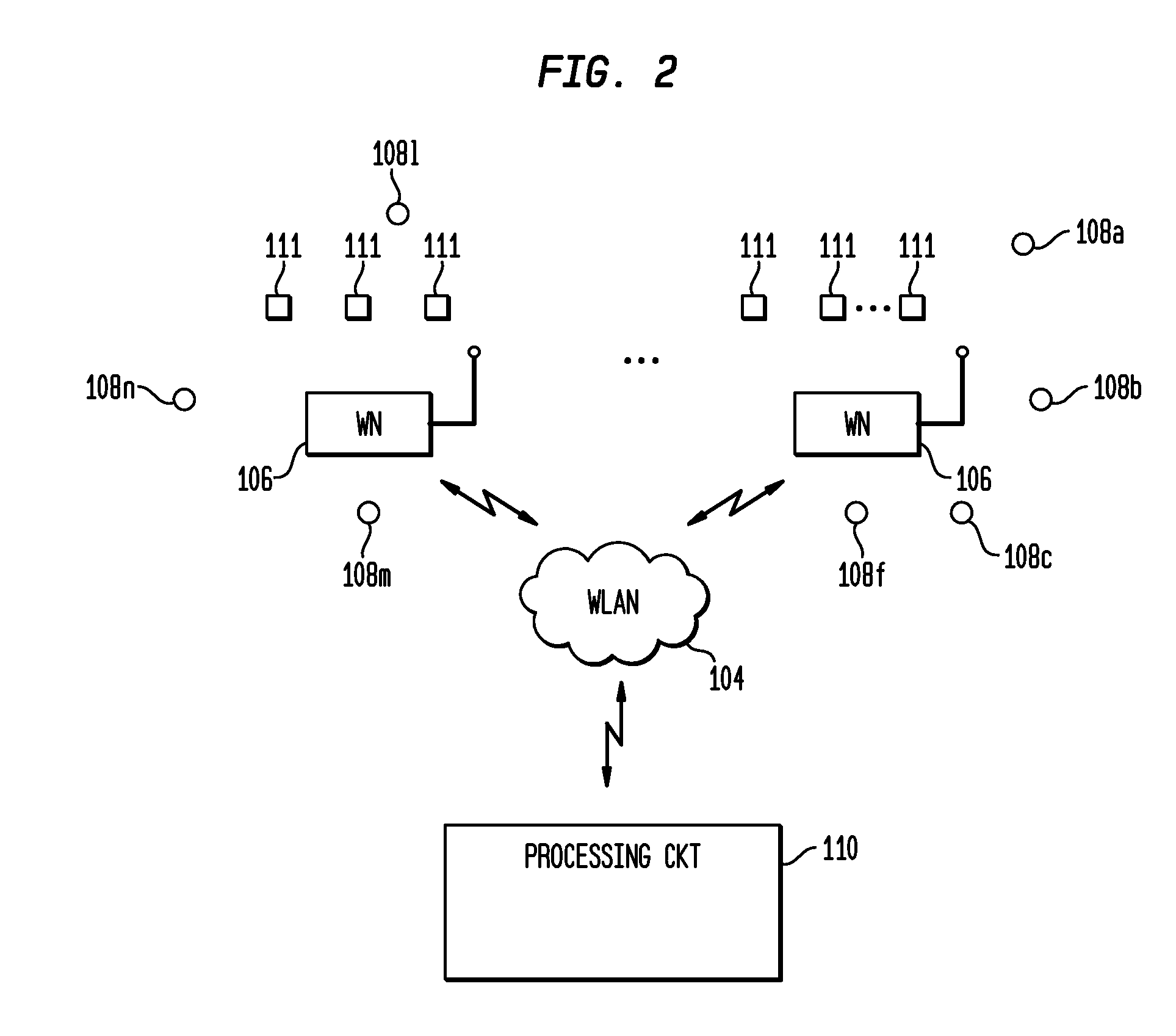
[0022]FIGS. 1 and 2 show an exemplary embodiment of an embodiment of the invention implemented in a portion of a building. More specifically, FIG. 1 shows a building system 100 in a portion or area 102 of a building that includes a communication network 104, a plurality of wireless nodes 106 within a building operably coupled to the communication network 104, a plurality of passive wireless devices 108a, 108b, . . . 108n, and a processing circuit 110. In this embodiment, the building system 100 also includes sensor units 111 disposed through the building area 102. FIG. 2 shows a schematic block diagram of the building system 100 of FIG. 1 apart from the building area 102.

[0023]Referring specifically to FIG. 1, the building area 102 includes a first space 112 in the form of an office, a second space 114 in the form of a conference room, and a third space 116 in the form of a hallway. The specifics of the layout of the building area 102 and spaces 112, 114 and 116 are given by way of ...


PUM


Abstract

A building system includes a communication network, a plurality of wireless nodes, a plurality of passive wireless devices, and a processing circuit. The plurality of wireless nodes are disposed within a building operably and are coupled to the communication network. Each of the passive wireless devices is affixed to or within an object within the building. At least some of the objects constitute fixtures within the building. Each passive wireless device contains first information regarding at least one property of the object, and is configured to communicate wirelessly to at least one of the wireless nodes using power derived from communication signals detected in the passive wireless device. The processing circuit operably is coupled to receive the first information from the wireless devices, the processing circuit configured to update a model of at least a portion of a building based at least in part on the at least one property of the objects.

Description

[0001]This application claims the benefit of U.S. Provisional Patent Application Ser. No. 61 / 093,816, filed Sep. 3, 2008, and which is incorporated herein by reference.FIELD OF THE INVENTION[0002]The present invention relates to building systems, building data modeling, and building automation.BACKGROUND OF THE INVENTION[0003]Building information modeling has been employed to assist in planning and implementation of various building systems. For example, it is known to provide building models during the development stage of a building project to aid in the selection of equipment, and to assist in formulating a construction plan. A building model will often contain granular details about the structural elements of a building, such as framing details, foundation details, wall details and the like.[0004]Existing building information models contain data identifying the two-dimensional or three-dimensional interrelationships among elements. Building models are typically stored as databas...

Claims


Application Information

Patent Timeline
Patent Type & Authority Applications(United States)
IPC IPC(8): G06F17/50F24F11/72F24F11/54F24F11/56H04W4/33
CPCH04L12/282H04L12/2823H04L67/12H04L2012/285H04W16/20H04L2012/2841H04L41/00H04L69/00
Inventor ROSCA, JUSTINIANAHMED, OSMANSASTRY, CHELLURY R.
Owner SIEMENS CORP
Why Eureka
Try Eureka