

Short circuit and open circuit protection for a boost converter
a short circuit and open circuit protection technology, applied in the field of boost converters, can solve the problems of damage to the power switch, damage to certain components, and inrush of huge amounts, and achieve the effect of preventing the damage of the open circuit and preventing the damage of the boost converter
- Summary
- Abstract
- Description
- Claims
- Application Information
AI Technical Summary
Benefits of technology
Problems solved by technology
Method used
Image

Examples
Embodiment Construction
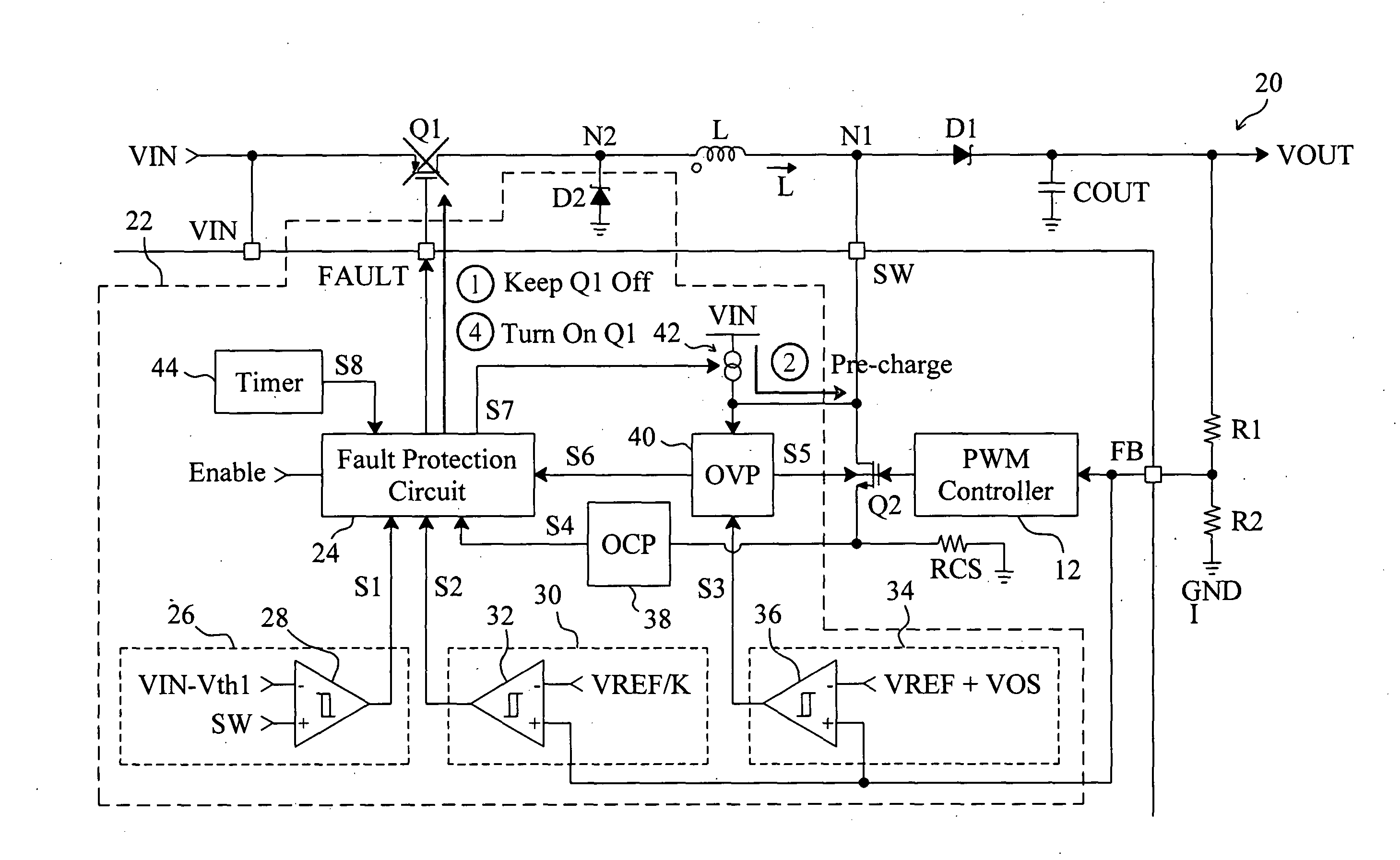
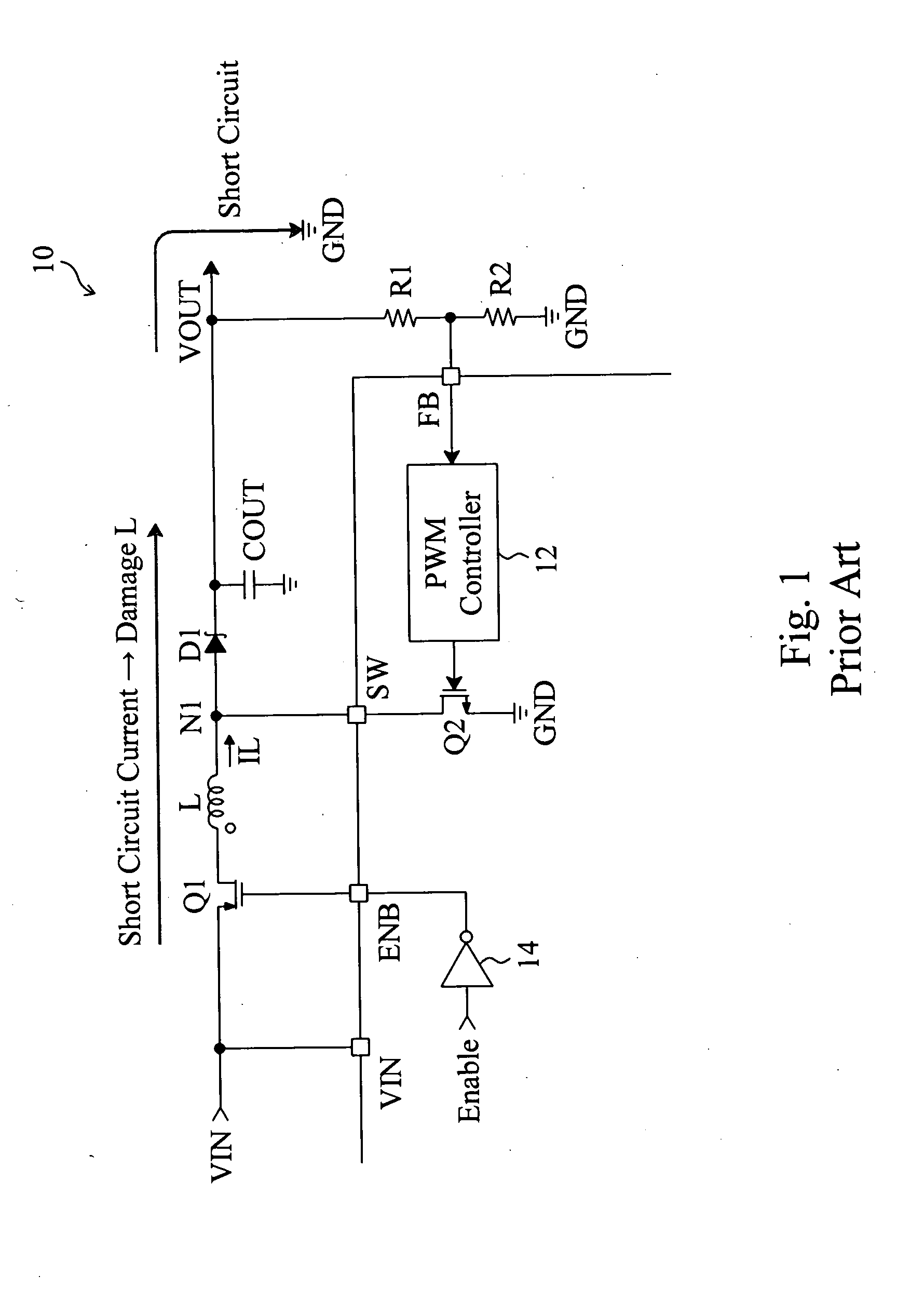
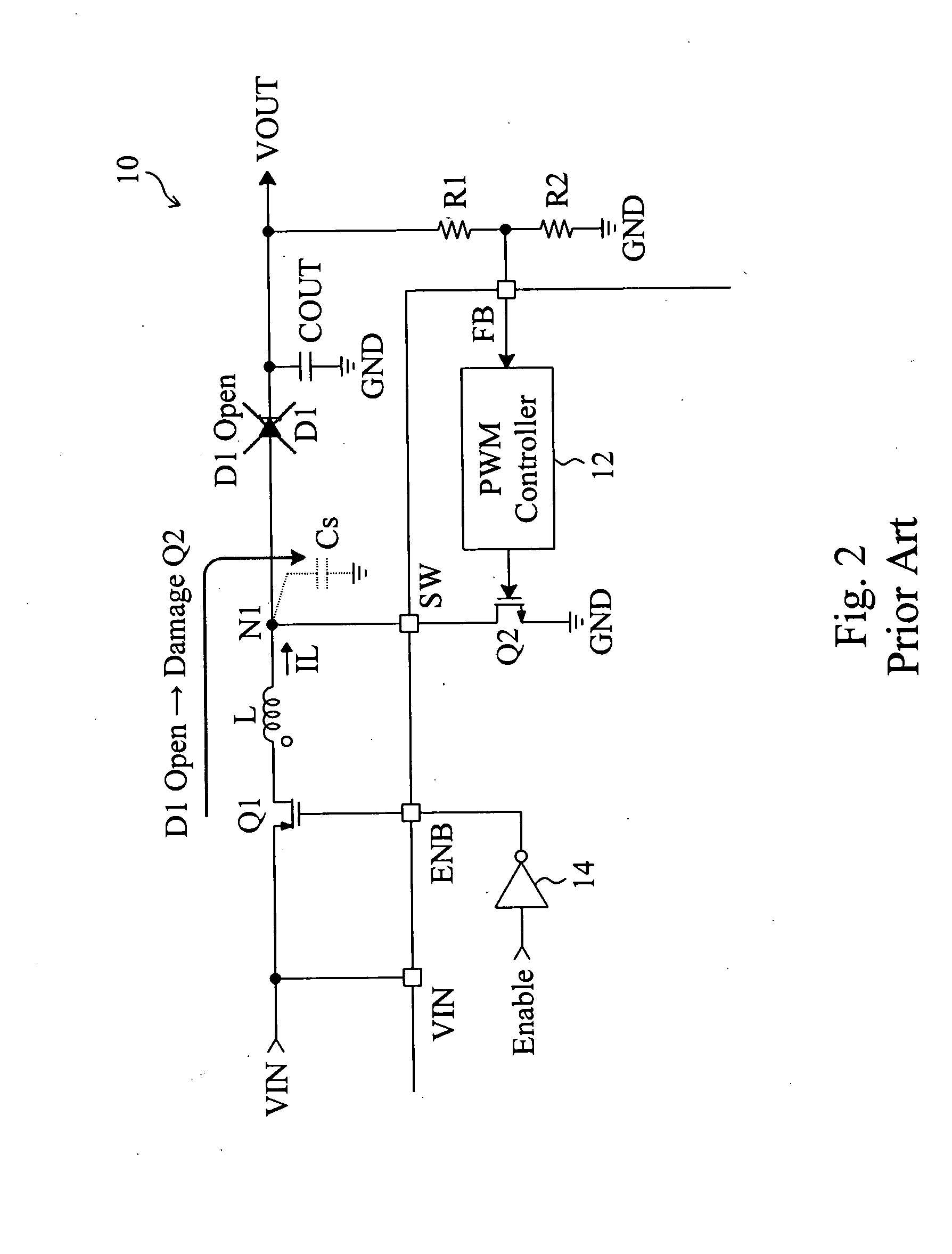
[0026]FIG. 3 is a circuit diagram of an embodiment according to the present invention based on the conventional boost converter 10 shown in FIG. 1, in which a boost converter 20 includes a protection apparatus 22 to provide open circuit and short circuit protection for the boost converter 20. The protection apparatus 22 monitors the voltage at the switching node N1 and the output voltage VOUT for open circuit and short circuit detection. If open circuit or short circuit is detected, the protection apparatus 22 will turn off the load disconnect switch Q1. The protection apparatus 22 includes a fault protection circuit 24 connected to the load disconnect switch Q1 to switch the load disconnect switch Q1. The voltage at the switching node N1 is monitored by monitoring the voltage of the switching pin SW which is connected to the switching node N1, and the output voltage VOUT is monitored by monitoring the feedback voltage FB produced by the voltage divider composed of resistors R1 and ...
PUM
 Abstract
Description
Claims
Application Information