

Non-volatile memory storage system
- Summary
- Abstract
- Description
- Claims
- Application Information
AI Technical Summary
Benefits of technology
Problems solved by technology
Method used
Image

Examples
Embodiment Construction
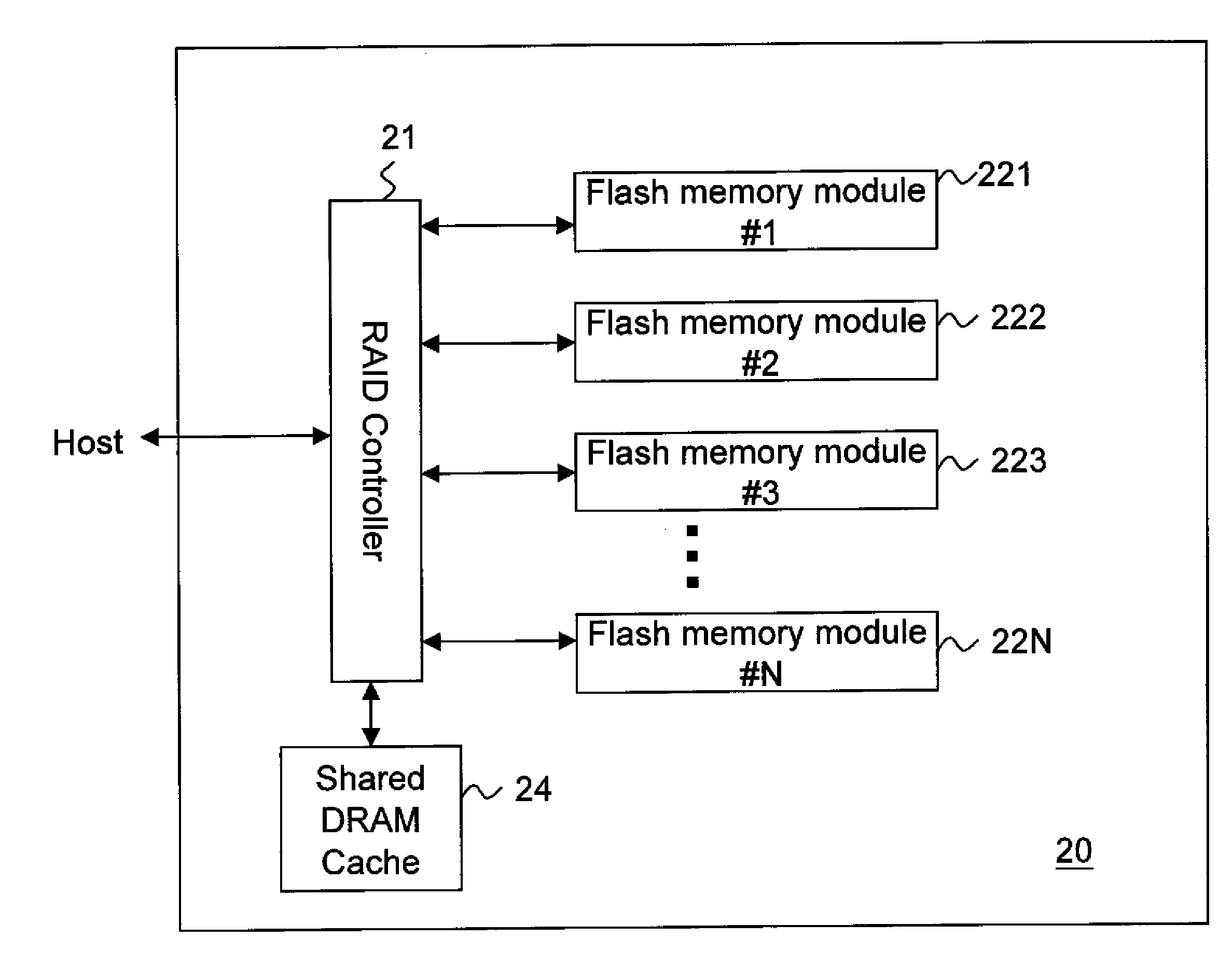
[0039]FIG. 2 is a schematic diagram showing a data storage system 20 according to a first embodiment of the present invention. The data storage system 20 includes a RAID controller 21, which controls several flash memory modules 221-22N. Each of the flash memory modules includes a flash memory controller and multiple flash memories. The flash memory modules can be in the form of SSD, EFD (Enterprise Flash Drive), or other types of flash memory cards. EFD performs ECC (Error Correction Code), wear-leveling and bad block management on the flash memories. EFD exhibits high reliability quality. The flash memory modules for example can be USB flash drive, card bus card, SD flash card, MMC flash card, memory stick, MI card, Expresscard flash card, and other types of flash memory cards. An example of the other type of flash memory card is down-grade memory cards. The down grade memory cards use down grade flash memories inside the memory cards. The down grade flash memories have some porti...
PUM
 Abstract
Description
Claims
Application Information