Load Control Device Having A Visual Indication of Energy Savings and Usage Information

a technology of energy saving and usage information, applied in the direction of process and machine control, testing/monitoring control system, instruments, etc., can solve problems such as energy was

Active Publication Date: 2010-05-27
LUTRON TECH CO LLC
View PDF28 Cites 101 Cited by
  • Summary
  • Abstract
  • Description
  • Claims
  • Application Information

AI Technical Summary

Benefits of technology

[0008]According to an embodiment of the present invention, a dimmer switch for controlling the amount of power delivered from a power source to a lighting load comprises a controllably conductive device, an intensity adjustment actuator, and a visual display for providing an indication of when a present intensity of the lighting load is above or below a predetermined eco-level intensity. The controllably conductive device is adapted to be coupled in series electrical connection between the source and the lighting load for controlling the intensity of the lighting load. The intensity adjustment actuator is operatively coupled to the controllably conductive device, such that the controllably conductive device can adjust the intensity of the lighting load between a low-end (or minimum) intensity and a high-end (or maximum) intensity in response to actuations of the intensity adjustment actuator. The visual display is illuminated in a first manner when the intensity of the lighting load is less than or equal to the eco-level intensity, and in a second manner when the intensity of the lighting load is greater than the eco-level intensity. The predetermined eco-level intensity is greater than approximately 75% of a maximum possible intensity of the lighting load.

Problems solved by technology

However, many users of dimmer switches unintentionally control the intensity of the lighting load to a level that is higher than actually needed, i.e., to a level that provides more light than is needed, thus, wasting energy.

Method used


Image

  • Load Control Device Having A Visual Indication of Energy Savings and Usage Information
  • Load Control Device Having A Visual Indication of Energy Savings and Usage Information
  • Load Control Device Having A Visual Indication of Energy Savings and Usage Information

Examples


first embodiment

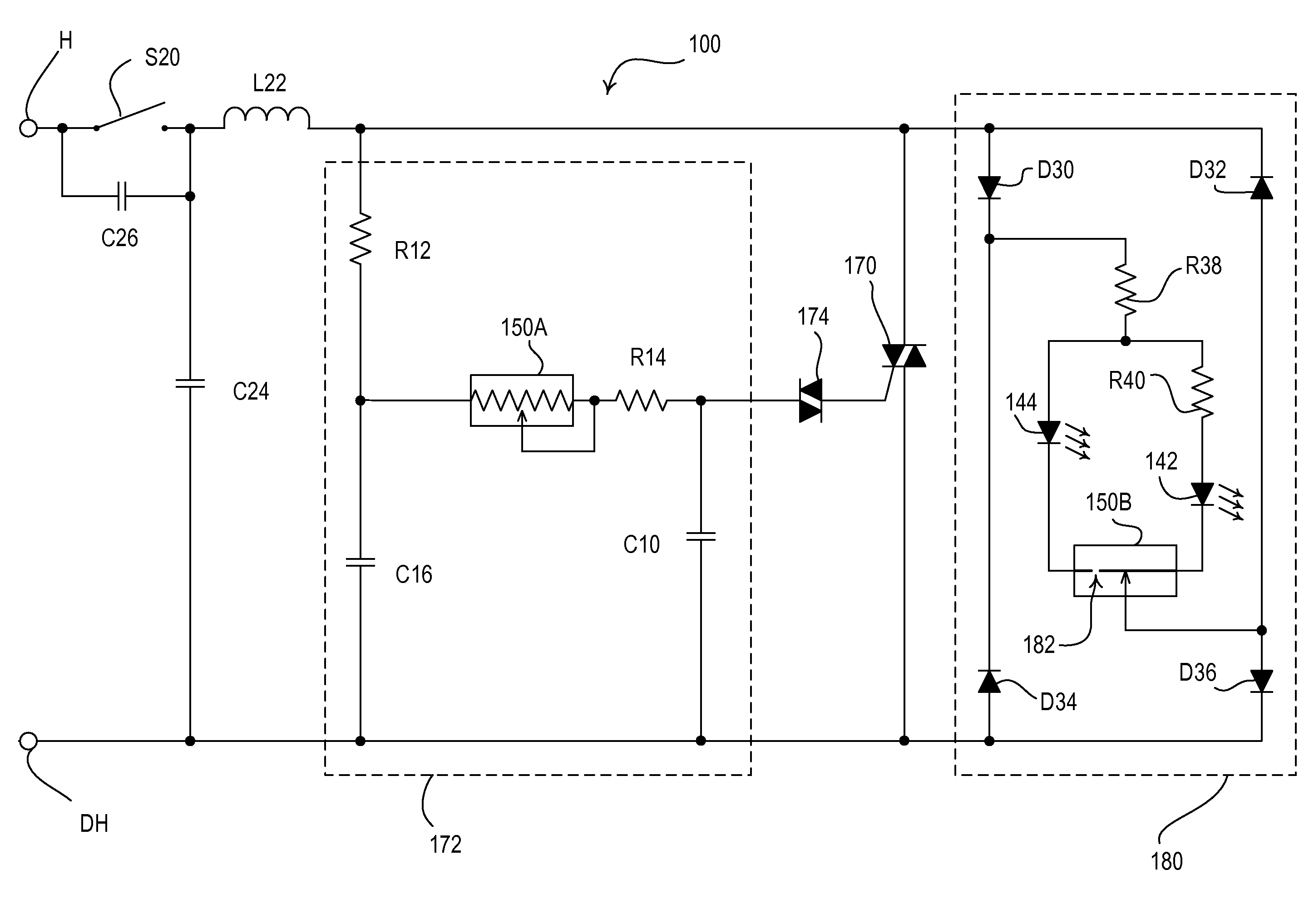
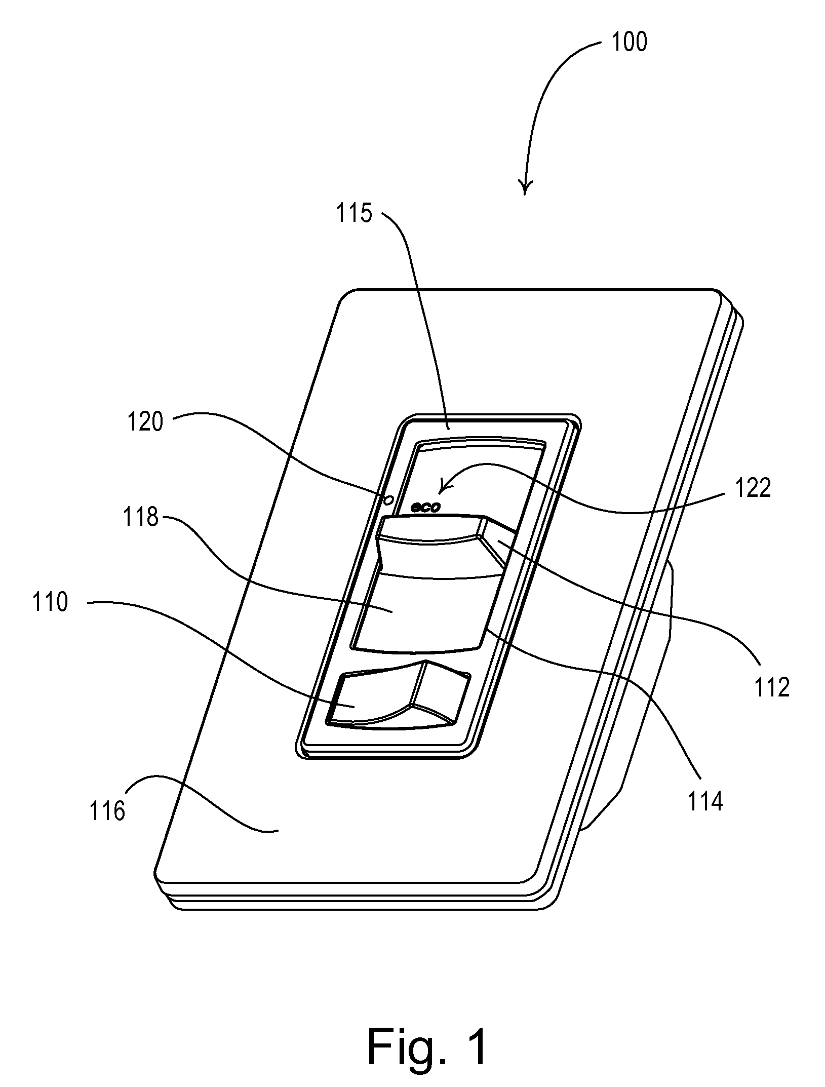
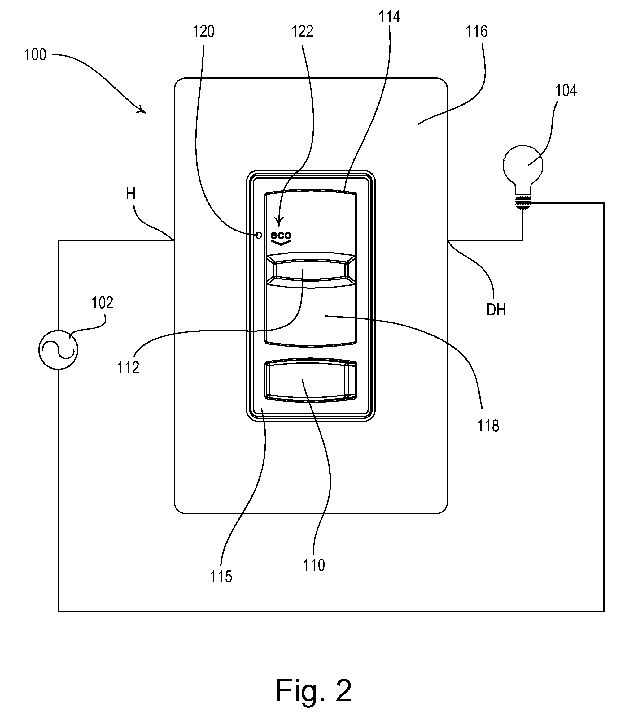
[0039]FIG. 1 is a perspective view of a dimmer switch 100 that provides a visual indication of energy savings and usage information according to the present invention. FIG. 2 shows a front view of the dimmer switch 100, which is coupled in series electrical connection between an alternating-current (AC) power source 102 and a lighting load 104 for control of the amount of power delivered to the lighting load. The dimmer switch 100 is coupled to the power source 102 via a hot terminal H and to the lighting load 104 via a dimmed hot terminal DH. Accordingly, the dimmer switch 100 is operable to turn the lighting load 104 on and off and to control a present lighting intensity L (i.e., a perceived lighting intensity) of the lighting load across a dimming range between a low-end lighting intensity LLE (e.g., approximately 5% of a maximum possible intensity LMAX) and a high-end lighting intensity LHE (e.g., approximately 92% of the maximum possible intensity LMAX). The maximum possible in...

second embodiment

[0061]FIG. 8 is a simplified flowchart of a control procedure 2000 executed periodically by the controller 234 of the dimmer switch 200 according to the present invention. The control procedure 2000 is executed by the controller 234, for example, once every half-cycle of the AC power source 202 when the zero-crossing detector 240 detects a zero-crossing at step 2010. If the controller 234 receives an input from the switch S20 at step 2012 (i.e., the rocker switch 110 was actuated) and the lighting load 104 is presently on at step 2014, the controller 234 controls the lighting intensity L of the lighting load to be off at step 2016. If the lighting load 204 is off at step 2014, the controller 234 sets the present intensity L in response to the voltage provided by the potentiometer 250 (i.e., the position of the slider knob 112) at step 2018. If the rocker switch 110 is not actuated at step 2012, a determination is made as to whether the position of the slider knob 112 has been adjust...

third embodiment

[0063]FIG. 9A is a front view and FIG. 9B is a right-side view of a slide-to-off dimmer switch 300 for providing a visual indication representative of energy savings and usage information according to the present invention. The dimmer switch 300 comprises a slider knob 310 adapted to slide along the length of an opening 312 of a faceplate 314. Adjustment of the slider knob 310 causes the dimmer switch 300 to adjust the amount of power delivered to the connected lighting load and thus the intensity of the lighting load. When the slider knob 310 is adjusted to the lowermost position, the dimmer switch 300 turns off the connected lighting load. The dimmer switch 300 further comprises a single visual indicator 320 on the slider knob 310, such that the visual indicator moves as the position of the slider knob is adjusted. The visual indicator 320 is illuminated to provide the visual indication of energy savings and usage information of the dimmer switch 300. Specifically, the dimmer swit...


PUM


Abstract

A dimmer switch for controlling the amount of power delivered to and thus the intensity of a lighting load comprises a visual display operable to provide a visual indication representative of energy savings and usage information. The visual display may comprise a single visual indicator or a linear array of visual indicators. The visual display is illuminated in a first manner when the intensity of the lighting load is less than or equal to a predetermined eco-level intensity, and is illuminated in a second manner when the intensity of the lighting load is greater than the eco-level intensity. For example, the single visual indicator may be illuminated a first color, such as green, when the intensity of the lighting load is less than or equal to the eco-level intensity, and illuminated a second different color, such as red, when the intensity of the lighting load is greater than the eco-level intensity.

Description

RELATED APPLICATIONS[0001]This application claims priority from commonly-assigned U.S. Provisional Application Ser. No. 61 / 117,624, filed Nov. 25, 2008, entitled LOAD CONTROL DEVICE THAT PROVIDES A VISUAL INDICATION OF ENERGY SAVING INFORMATION, and U.S. Provisional Application Ser. No. 61 / 139,206, filed Dec. 19, 2008, entitled LOAD CONTROL DEVICE PROVIDING A VISUAL INDICATION OF ENERGY USAGE INFORMATION. The entire disclosures of both applications are hereby incorporated by reference.BACKGROUND OF THE INVENTION[0002]1. Field of the Invention[0003]The present invention relates to a load control device for controlling the amount of power delivered to an electrical load, and more particularly, to a dimmer switch having a visual display, such as a single visual indicator or a linear array of visual indicators, for providing a visual indication of energy savings or usage information.[0004]2. Description of the Related Art[0005]A conventional wall-mounted load control device is mounted t...

Claims


Application Information

Patent Timeline
Patent Type & Authority Applications(United States)
IPC IPC(8): H05B37/02
CPCH01H9/181H05B39/085H01H2231/052H01H15/025
Inventor ALTONEN, GREGORYJACOBY, ELLIOT G.SALVESTRINI, CHRISTOPHER JAMESSPIRA, JOEL S.
Owner LUTRON TECH CO LLC
Why Eureka
Try Eureka