RFID systems

a technology of radio frequency identification and system, applied in the field of radio frequency identification system, can solve the problems of affecting the use of passive tags, the theoretical lifetime of active tags is limited by the battery life, and the cost causes different applications

Inactive Publication Date: 2010-05-27
REDBITE SOLUTIONS
View PDF21 Cites 38 Cited by
  • Summary
  • Abstract
  • Description
  • Claims
  • Application Information

AI Technical Summary

Benefits of technology

[0028]In embodiments of the above-described systems a tag is writable and the communications network and tag are configured for writing data to the tag. This is particularly advantageous as data writing tends to be particularly range-constrained and thus embodiments of the invention can provide particularly useful advantages.

Problems solved by technology

Furthermore, an active tag has theoretical lifetime limited by the battery life whereas a passive tag does not suffer that limitation.
The difference in cost causes different application.
In real industrial deployment, the use of passive tags is affected by several problems including deployment of tags in RF noisy environment, lower performance for high volume of tags in a given area etc.
Broadly speaking one problem is how to match, at a stage in the supply chain, goods specified in an advance shipping notice with actual goods received, prior to passing the goods onto a subsequent party in the supply chain.
This is a difficult problem because, broadly speaking, a tag merely provides a number or a set of numbers and in many environments, when a tag is read RFID signals from unwanted tags may erroneously be detected.
More particularly, in the example of a tagged pallet, bearing tagged cases, storing tagged items there is considerable potential for confusion between signals from different pallets / cases / items.
ALSO determining the location of tagged items using mobile RFID reader is difficult as it is difficult to determine the exact location of the moving reader.
This problem is even more challenging with UHF RFID system where the read zone of mobile RFID reader can go up to 2-3 metres range.

Method used


Image

  • RFID systems
  • RFID systems
  • RFID systems

Examples


Embodiment Construction

[0055]Advanced Features

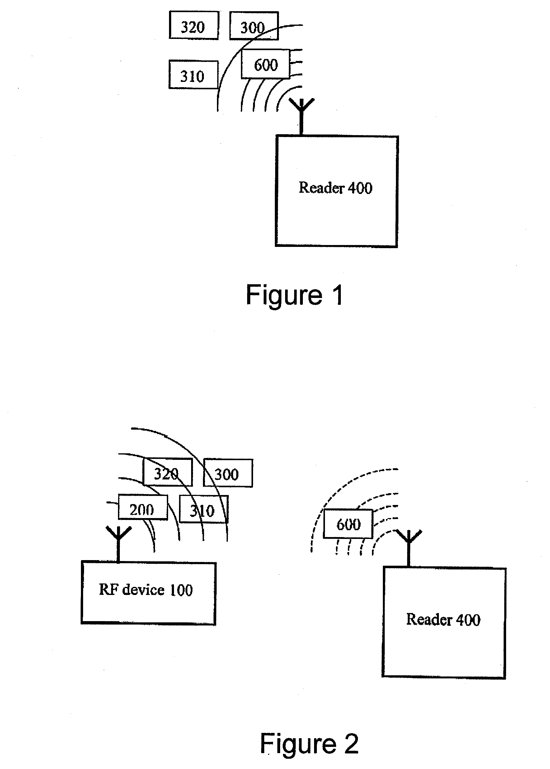
[0056]Embodiments of the invention relate to passive RFID tag(s) and its related peripheral devices. The tag communicates with conventional RFID readers following well-defined communication protocols. FIG. 1 illustrates this communication mode. Specifically, our passive tags (300, 310 and 320) are energised by the RF waves (600) transmitted from the conventional RFID reader (400), once the received RF power is beyond a predefined level. The reader sends command by modulating the RF (600) and the tags alternates their reflection features in replying the reader's request. In this respect the tags provide backward compatibility.

[0057]FIG. 2 illustrates the case of using RF waves (200) transmitted from other devices (100) to energise passive tags 300, 310 and 320). Once energised, the passive tags (300, 310 and 320) may communicate with the inquiring RFID reader (400) following data communication protocols, even if the RF power (600) received from the inquiring RF...


PUM


Abstract

We describe an RFID communications network comprising: a plurality of passive RFID tags; at least one RF power supply device; and at least one RFID reader; and wherein a said RFID tag is configured to use a first frequency to receive power for powering said tag from said RF power supply device and to use a second, different frequency to communicate with said RFID reader; and wherein said plurality of RFID tags are configured to use the same said first frequency to receive said power, and all use different second frequencies to communicate with said RFID reader. The tags may be used to generate probability data, the probability data for a said identified tag being dependent upon a probability of the tag belonging to a collection the contents of which are to be verified; contents of the collection may then be verified against a schedule using processed verification data.

Description

FIELD OF THE INVENTION[0001]The present invention relates to Radio Frequency Identification (RFID) systems and in particular i) to the addition of some advanced features of high cost active tags to a low cost passive tag; ii) where the environment is such that signals may be received from a range of tags, some of them being unwanted; and iii) techniques for locating product tags when a mobile or handheld tag reader is employed.BACKGROUND TO THE INVENTION[0002]Background prior art can be found in: US2005 / 110636; WO01 / 95242; U.S. Pat. No. 5,838,235; U.S. Pat. No. 4,857,893; GB1290097; JP2007 / 067791; US2005 / 128055; WO2000 / 10144; US2007 / 0126634; GB2433178; WO2007 / 106972; US2007 / 188342; US2005 / 246092; JP2007 / 219736; and JP2006 / 221541.[0003]RFID systems rely on radio frequency-based communication between a reader and a transponder or tag of various types for identifying objects and have a variety of applications. Categorically; there are two types of RFID tags: active and passive. An acti...

Claims


Application Information

Patent Timeline
Patent Type & Authority Applications(United States)
IPC IPC(8): H04Q5/22G08B13/14G08B5/22
CPCG06K7/0008G06K7/10069G06K7/10217G06Q10/08H04Q2209/88G06Q50/30H04Q9/00H04Q2209/47G06Q10/087
Inventor WONG, ALEX C.Y.
Owner REDBITE SOLUTIONS
Why Eureka
Try Eureka