
Light-emitting device of portable communication terminal

a technology of portable communication terminal and light-emitting device, which is applied in the direction of instruments, lighting and heating equipment, mechanical equipment, etc., can solve the problems of increased fabrication cost and complex assembly process, and achieve the effect of improving aesthetic sense and cleaning the exterior design of the portable communication terminal

Active Publication Date: 2010-05-27
SAMSUNG ELECTRONICS CO LTD
View PDF2 Cites 12 Cited by
  • Summary
  • Abstract
  • Description
  • Claims
  • Application Information

AI Technical Summary

Benefits of technology

[0011]An exemplary aspect of the present invention is to provide at least the advantages described below. Accordingly, one exemplary aspect of the present invention is to provide a light-emitting device of a portable communication terminal obscures the position of a light-diffusing portion when viewed from the outside in a non-light emission state by integrally forming the light-diffusing portion on a main body housing, so as to provide a clean exterior design of the portable communication terminal, and improve an aesthetic sense.
[0012]Another exemplary aspect of the present invention is to provide a light-emitting device of a portable communication terminal that can provide a clean exterior design in a non-light emission state by applying a Non-conductive Vacuum Metallization (NCVM) process to a light-diffusing portion to be integrally formed on a main body housing, and that can improve an exterior design and an aesthetic sense of the portable communication terminal by emitting light through the light-diffusing portion covered with an NCVM surface in a light emission state.

Problems solved by technology

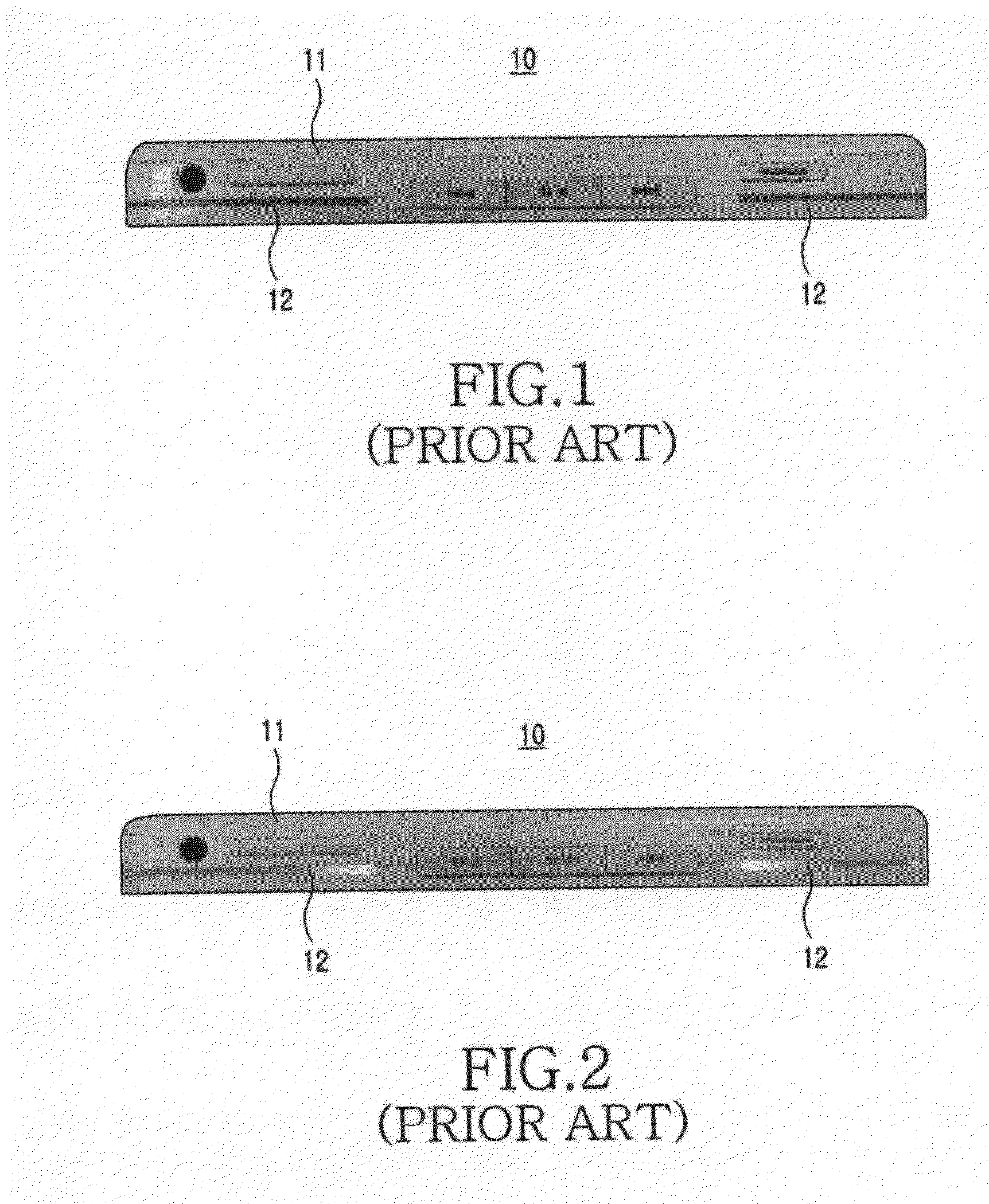
Since the light-transmitting portion 12 is separately mounted on the main body housing 11 and a process for coupling the light-transmitting portion 12 along a coupling line of the main body housing 11 is added to an assembly process of manufacturing the portable communication terminal, the assembly process is complex and the fabrication cost are increased as a result.

Method used


Image

  • Light-emitting device of portable communication terminal
  • Light-emitting device of portable communication terminal
  • Light-emitting device of portable communication terminal

Examples


Embodiment Construction

[0029]A first exemplary embodiment of the present invention will now be described in detail with reference to FIGS. 3 to 8.

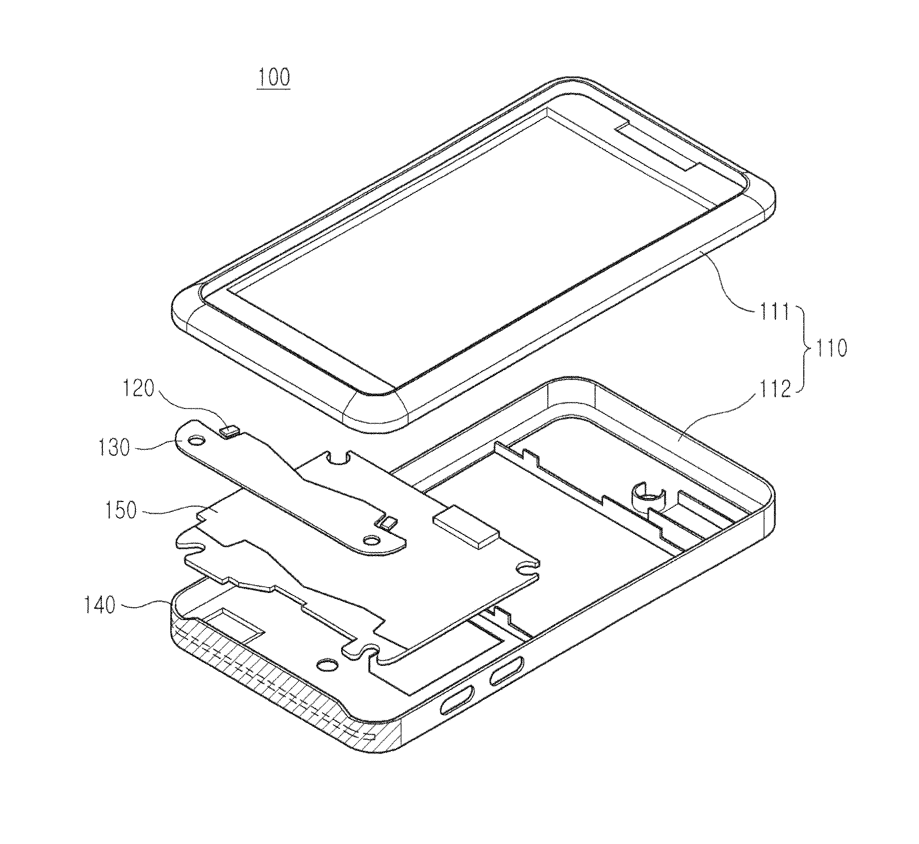
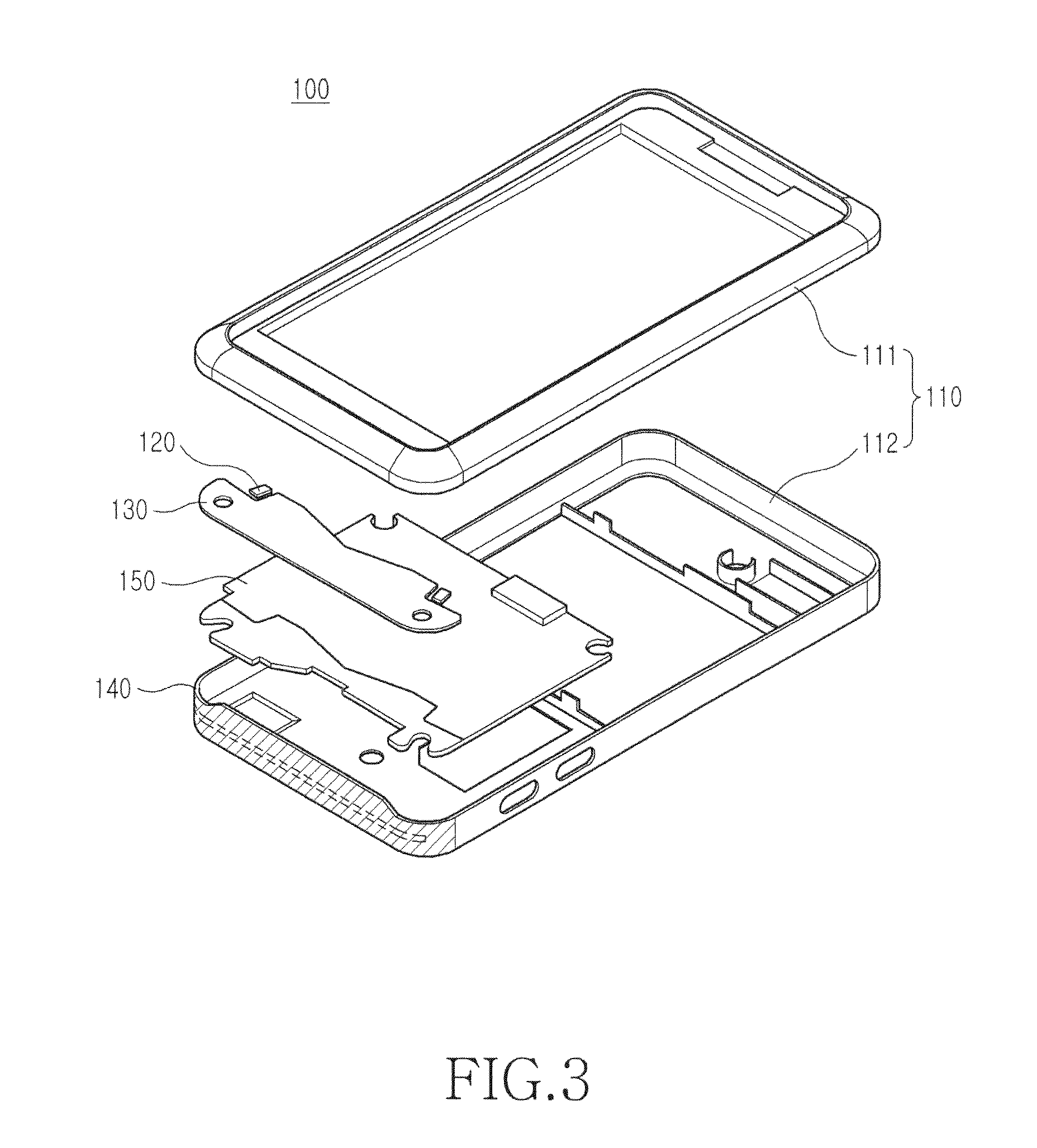
[0030]As illustrated in FIGS. 3 to 6, a light-emitting device 100 of a portable communication terminal typically includes a housing 110, a light-emitting element 120 for emitting light, a light guide sheet 130 for guiding the light from the light-emitting element 120, and a light-transmitting portion 140. The light-transmitting portion 140 is integrally formed on the housing 110 and transmits the light from one end of the light guide sheet 130 to an outer side of the housing 110. As illustrated in FIG. 6, a through-hole 112a through which the light from the one end of the light guide sheet 130 passes is formed in the housing 110 and is covered with the light-transmitting portion 140. The through-hole 112a can be formed in a coupling surface direction of the housing 110 to one side surface thereof.

[0031]As illustrated in FIGS. 4 and 6, the light-transmitting port...


PUM


Abstract

A light-emitting device of a portable communication terminal improves exterior decoration by emitting light to the exterior of the portable communication terminal and implements a sense of unity of a design in a non-light emission state by integrating a portion to which the light is transmitted with a main body housing. The light-emitting device includes a housing, a light-emitting element for emitting light, a light guide sheet for guiding the light from the light-emitting element, and a light-transmitting portion integrally formed on the housing for transmitting the light from one end of the light guide sheet to an outer side of the housing. A sense of unity of the main body housing and the light-transmitting portion can be improved by applying a non-conductive vacuum metallizing (NCVM) process to the exterior. An aesthetic sense is improved with the sense of unity of the exterior design.

Description

CLAIM OF PRIORITY[0001]This application claims the benefit under 35 U.S.C. §119(a) from a Korean Patent Application filed in the Korean Intellectual Property Office on Nov. 26, 2008 and assigned Serial No. 10-2008-0118293, the disclosures of which are incorporated herein by reference in its entirety.BACKGROUND OF THE INVENTION[0002]1. Field of the Invention[0003]The present invention relates generally to a light-emitting device of a portable communication terminal. More particularly, the present invention relates to a light-emitting device of a portable communication terminal that can improve exterior decoration by emitting light to the exterior of the portable communication terminal and implement a sense of unity of a design and improve an aesthetic sense of an exterior design.[0004]2. Description of the Related Art[0005]Portable electronic devices, such as an MPEG audio layer-3 (MP3) player, a plasma display panel (PDP), a portable communication terminal, and a personal digital as...

Claims


Application Information

Patent Timeline
Patent Type & Authority Applications(United States)
IPC IPC(8): F21V8/00
CPCG02B6/0088H04M1/22H04M1/0283
Inventor MOON, TAE-HWALEE, JOON-YOUNGKIM, KYOUNG-JONGKIM, JIN-WOO
Owner SAMSUNG ELECTRONICS CO LTD
Learn More