Tube loading assembly for peristaltic pump

a technology of peristaltic pumps and loading assemblies, which is applied in the direction of flexible member pumps, machines/engines, positive displacement liquid engines, etc., can solve the problems of difficult production and use, difficult to make and use, and compromised structural simplicity, etc., to achieve easy operation, simple mechanical design, and avoid finger pinching

Active Publication Date: 2010-05-27
MOU DUEN GANG
View PDF7 Cites 53 Cited by
  • Summary
  • Abstract
  • Description
  • Claims
  • Application Information

AI Technical Summary

Benefits of technology

The present invention relates to a peristaltic pump that has been designed to be easier to load and operate than previous versions. A unique feature is a swinging tube pressing member that can safely release the tube when it needs to be replaced. Another advantage is that the pump distributes its force evenly along the length of the tube, reducing damage to the flexible part and allowing for better movement of fluids within the system. Additionally, the invention makes replacing parts faster and more convenient compared to older designs.

Problems solved by technology

The technical problem addressed in this patent is to create a peristaltic pump that is easy to use and load with a disposable tube section, without being prone to finger pinching or aggravating the tubing flex or fluid pressure pulsation problem.

Method used


Image

  • Tube loading assembly for peristaltic pump
  • Tube loading assembly for peristaltic pump
  • Tube loading assembly for peristaltic pump

Examples


Embodiment Construction

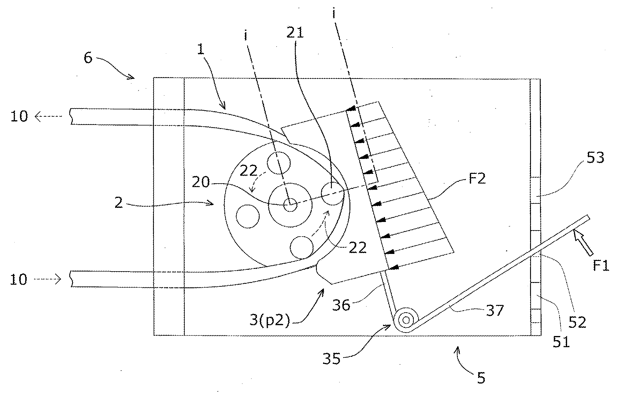
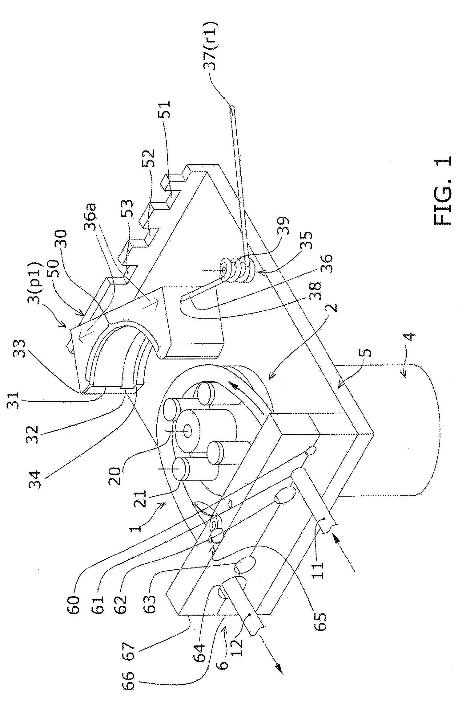
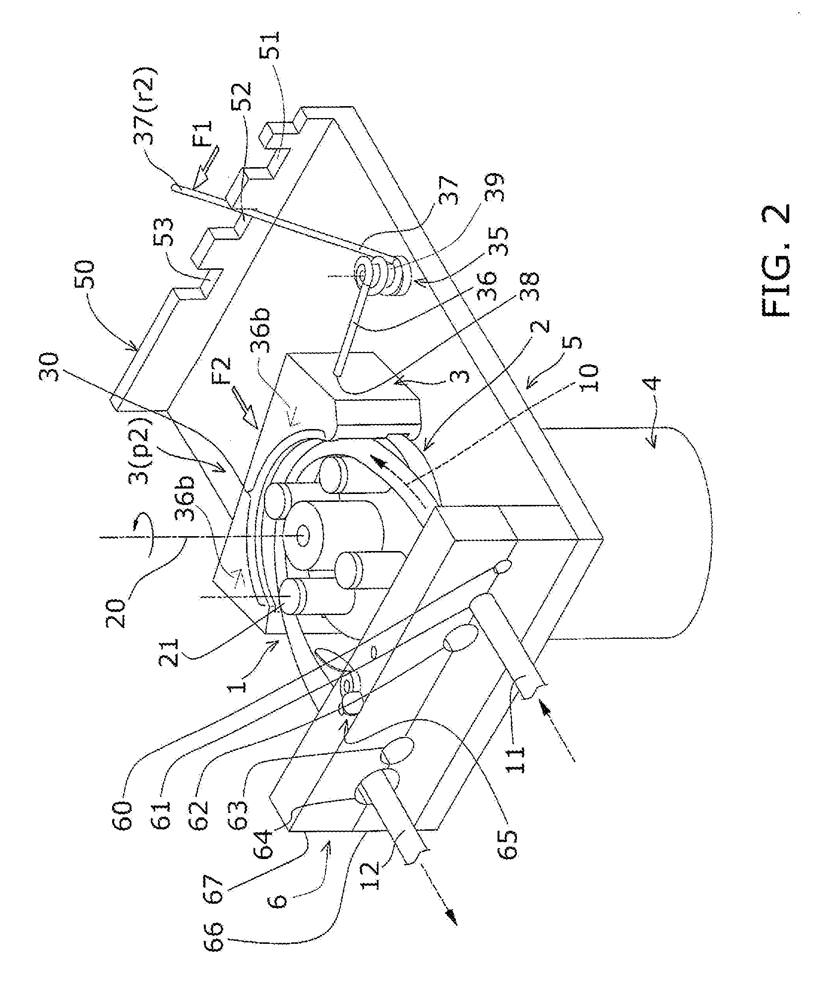
[0018]As shown in FIGS. 1 and 2, a peristaltic pump assembly in accordance with the present invention includes a base plate 5, a motor 4, a rotor assembly 2 with a plurality of circulating rollers 21, and a tube pressing member 3 with an arcuate side 30 forming a tube track 31. In such arrangement, the space between the rollers 21 on the rotor assembly 2 and the pressing member 3 is less than the diameter of the tube 1 and the tube 1 must be squeezed in between. The pump assembly of the present invention in an open (or unlocked) position with a tube section in place is shown in FIG. 1. An elastic tube section 1 is installed between a plurality of freely rotating rollers 21 installed on a rotor assembly 2 circulating about an axis 20 and a tube track 31 formed on a tube pressing member 3. The tube pressing member3 is pressed and locked in the proximity of the circular orbit of the rollers 21 by force from a two-arm helical torsion spring 35 pivotally mounted on a bolt 39 fixed to the...


PUM


Abstract

A spring mounted tube pressing member for peristaltic pumps allows loading and unloading of an elastic tube section between the tube pressing member and a continuously revolving rotor assembly by selectively moving between a locked position for fluid transfer and an open position for unhindered mounting and demounting of the tube section or a replaceable tube cassette. Not only is the pressure on the tube pressing member adjustable by the spring used, its dynamic pressure distribution on the tube section also prolongs the tube flex life and reduces fluid back mixing and pulsation in the tube.

Description


Claims


Application Information

Patent Timeline
Owner MOU DUEN GANG
Why Eureka
Try Eureka