Method and system for protection switching in ethernet ring

a protection switching and ethernet ring technology, applied in data switching networks, frequency-division multiplexes, instruments, etc., can solve problems such as inability to guarantee perfect connectivity between nodes, inability to fully respond to the entire network, and inability to connect to 8032 nodes

Inactive Publication Date: 2010-06-03
ELECTRONICS & TELECOMM RES INST
View PDF10 Cites 29 Cited by
  • Summary
  • Abstract
  • Description
  • Claims
  • Application Information

AI Technical Summary

Benefits of technology

[0016]An aspect of the present invention provides a method and system for protection switching in Ethernet rings capable of actively se...

Problems solved by technology

However, if a fault occurs in a shared link and both Ethernet rings perform protection switching, the RPLs of the first and second Ethernet rings would both be released to form a super-loop as shown in FIG. 1(c), causing the entire network to be irresponsive due to broadcast storming.
However, this method has a problem in that if another fault occurs in local links other than t...

Method used


Image

  • Method and system for protection switching in ethernet ring
  • Method and system for protection switching in ethernet ring
  • Method and system for protection switching in ethernet ring

Examples


Embodiment Construction

[0026]Exemplary embodiments of the present invention will now be described in detail with reference to the accompanying drawings. The invention may however be embodied in many different forms and should not be construed as limited to the embodiments set forth herein. Rather, these embodiments are provided so that this disclosure will be thorough and complete, and will fully convey the scope of the invention to those skilled in the art. In the drawings, the shapes and dimensions may be exaggerated for clarity, and the same reference numerals will be used throughout to designate the same or like components.

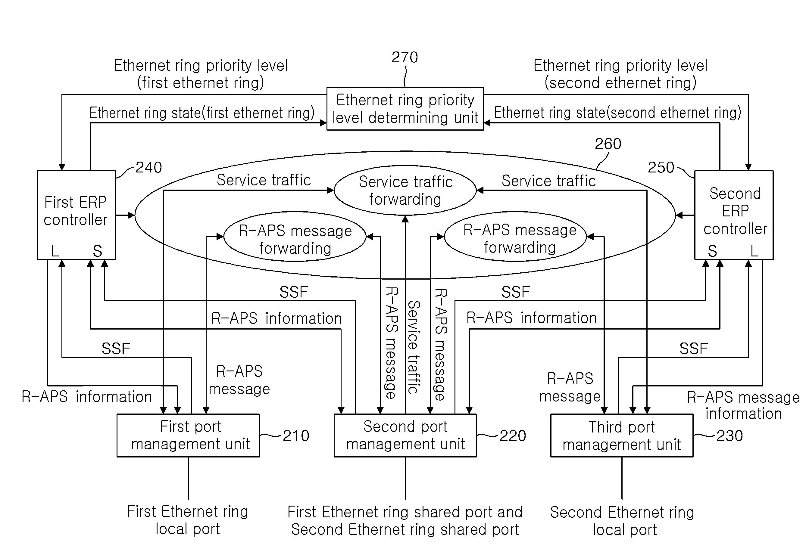
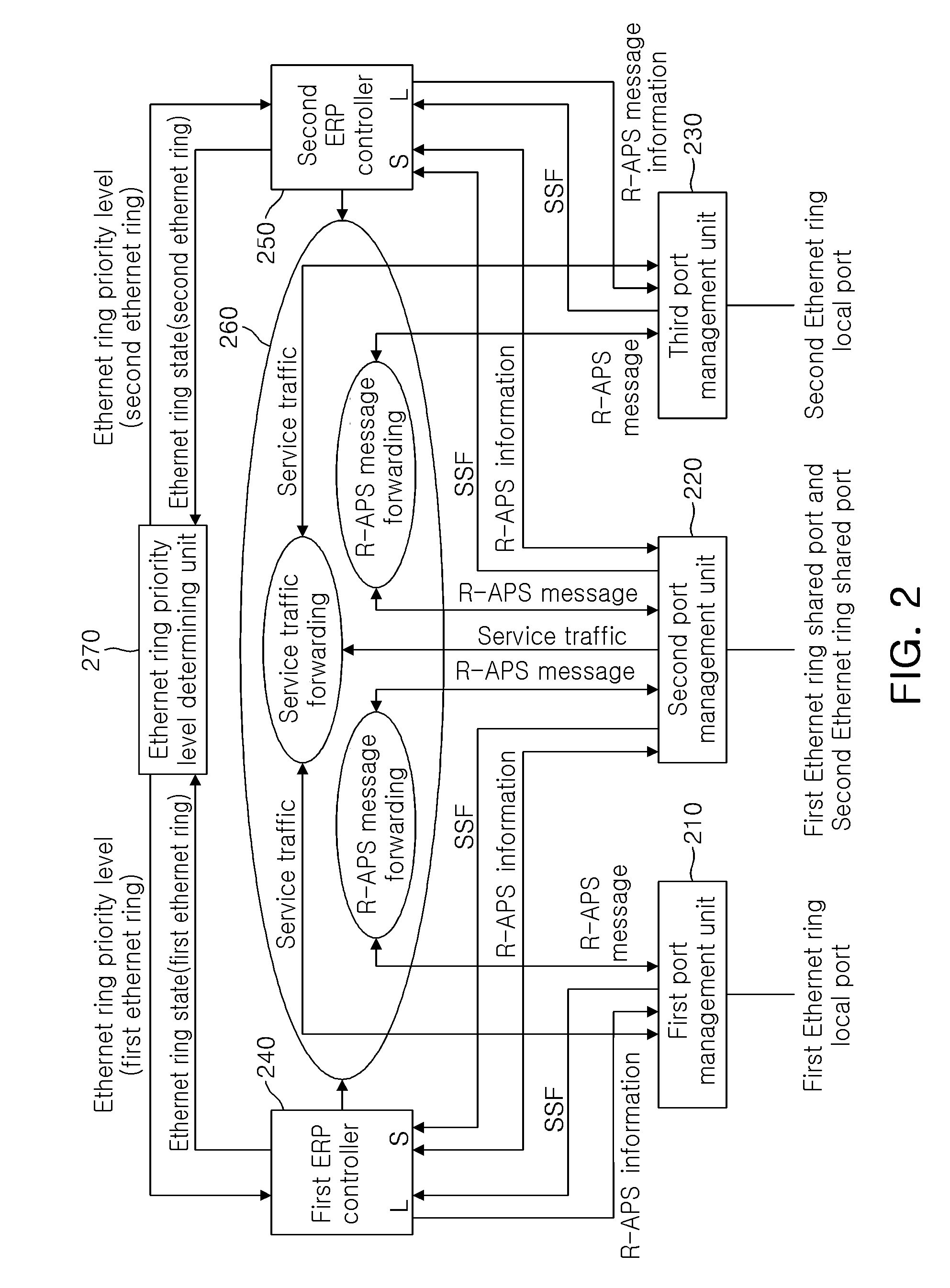
[0027]In an exemplary embodiment of the present invention, two interconnected Ethernet rings will be taken as an example for the sake of brevity. When N number of Ethernet rings are shared by a single shared link, (N+1) number of port management units and N number of Ethernet ring protection (ERP) controllers may be extendedly provided. A forwarding unit interworks with the (N+1) nu...


PUM


Abstract

A method and system for protection switching in Ethernet rings are disclosed. The method for protection switching in Ethernet rings includes: receiving a server signal fail (SSF), an Ethernet lower layer fault signal, a remote defect indication (RDI) for informing a different port about a fault state when a uni-directional fault is generated, and ring-automatic protection switching (R-APS) information for requesting Ethernet ring protection switching; comparing the SSF, the RDI, and the R-APS information, and setting states of the first and second Ethernet rings; determining a protection switching priority level of each of the first and second Ethernet rings according to the states of the first and second Ethernet rings; and performing protection switching on the first and second Ethernet rings according to their protection switching priority levels.

Description

CROSS-REFERENCE TO RELATED APPLICATIONS[0001]This application claims the priorities of Korean Patent Application No. 10-2008-0121251 filed on Dec. 2, 2008 and Korean Patent Application No. 10-2009-0027976 filed on Apr. 1, 2009, in the Korean Intellectual Property Office, the disclosures of which are incorporated herein by reference.BACKGROUND OF THE INVENTION[0002]1. Field of the Invention[0003]The present invention relates to a method and system for protection switching in an Ethernet ring and, more particularly, to a method and system for supplementing and improving a protection switching method in an interconnected Ethernet ring defined in ITU-T recommendation G.8032 Version 2.[0004]2. Description of the Related Art[0005]ITU-T recommendation G.8032 designates one of a plurality of links constituting an Ethernet ring as a ring protection link (RPL) and anode connected to one of both ports of the RPL as an RPL owner, so that the RPL owner can usually block the RPL to prevent a loop...

Claims


Application Information

Patent Timeline
IPC IPC(8): G06F11/00
CPCH04L12/4625H04L12/437
Inventor CHEUNG, TAE SIKKIM, DO YEONAHN, BYUNG JUN
Owner ELECTRONICS & TELECOMM RES INST
Why Eureka
Try Eureka