Common Module Stack Component Design

a technology of common modules and components, applied in the direction of cell components, indirect fuel cells, electrochemical generators, etc., can solve the problems of intermittent power availability, adverse effects of electricity on many devices, and the use of flow batteries as uninterruptible power supplies

Inactive Publication Date: 2010-06-03
IMERGY POWER SYST
View PDF2 Cites 92 Cited by
  • Summary
  • Abstract
  • Description
  • Claims
  • Application Information

AI Technical Summary

Problems solved by technology

Many devices that operate on electricity are adversely affected by the sudden removal of their power supply.
Flow batteries can be utilized as uninterruptible power supplies in place of more expensive backup generators.
Such batteries can also be utilized for providing an uninterruptible power supply in developing countries, many of which do not have reliable electrical power sources resulting in intermittent power availability.
These components may require many dedicated production tools and can cause an increase in production cost and complexity.
Furthermore, the integration of these various types of components into a flow battery stack can increase the number of potential failure points that can reduce the efficiency of a flow battery.

Method used


Image

  • Common Module Stack Component Design
  • Common Module Stack Component Design
  • Common Module Stack Component Design

Examples


Embodiment Construction

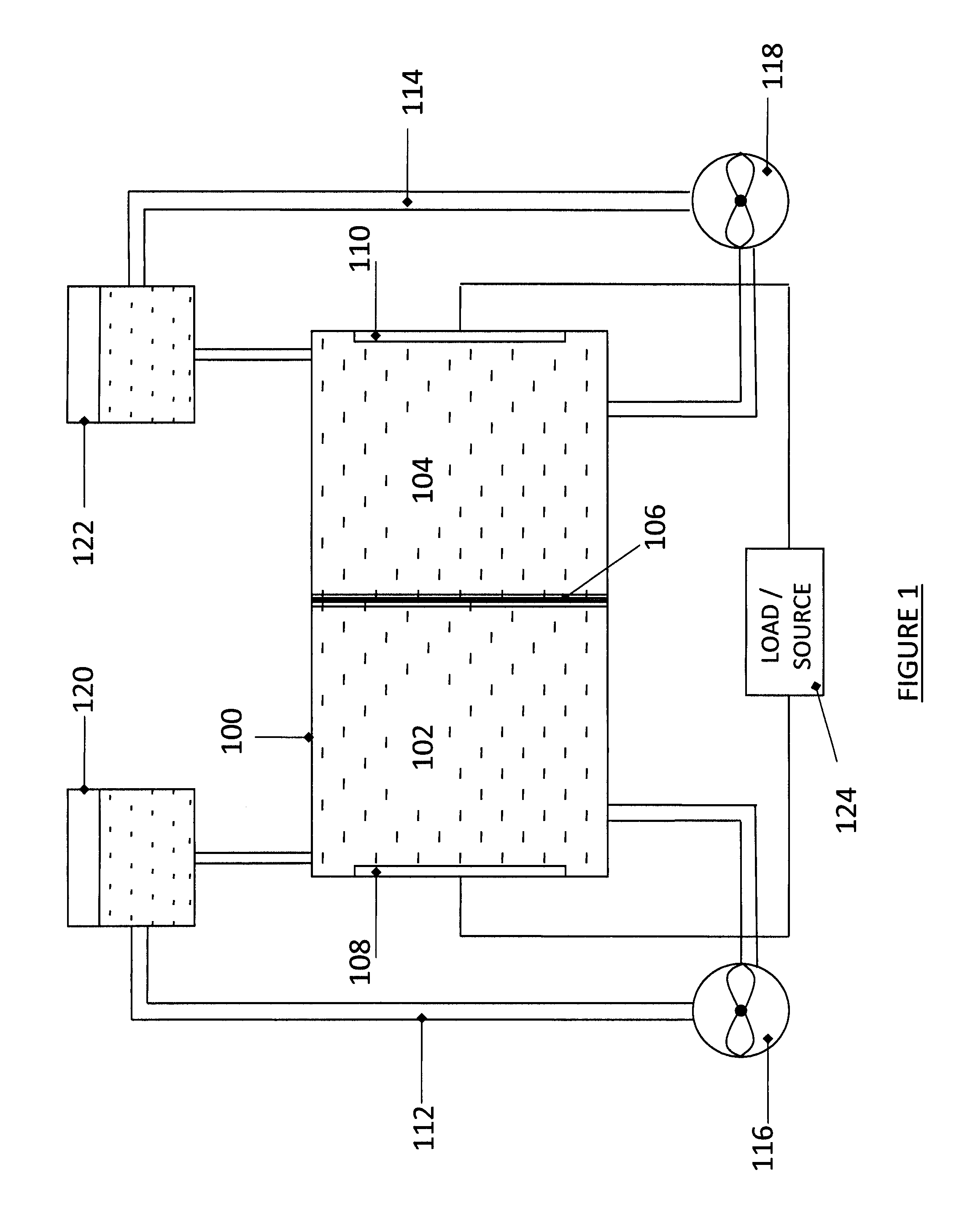
[0021]A flow cell is the minimal component of a flow battery. Multiple flow cells can be coupled (e.g., “stacked”) to form a multi-cell battery. The cell includes two half-cells, each with an electrode, separated by a membrane, through which ions are transferred during a reduction-oxidation (redox) reaction. One half-cell contains the anolyte and the other half-cell contains the catholyte. The electrolytes (i.e., anolyte and catholyte) are flowed through the half-cells, often with an external pumping system. Electrodes in each half cell provide surfaces on which the redox reaction takes place and from which charge is transferred.

[0022]FIG. 1 illustrates a flow cell 100 consistent with some embodiments of the present invention. Flow cell 100 includes two half-cells 102 and 104 separated by an ion exchange membrane (IEM) 106. Half-cells 102 and 104 include electrodes 108 and 110, respectively, in contact with an electrolyte 130 and 132, respectively, such that an anodic reaction occur...


PUM

PropertyMeasurementUnit
rotationaaaaaaaaaa
surface featureaaaaaaaaaa
electrical energyaaaaaaaaaa

Abstract

A stack for use in a flow battery, the stack comprising an odd number of interior elements positioned between two end elements, the two end elements each including an electrode, and the odd number of interior elements including membrane elements alternating with electrode elements, wherein the membrane elements include an interior frame and a membrane, the electrode elements include the interior frame and an electrode, wherein the interior frame is rotated by 180° from the frame of the membrane elements.

Description

CROSS-REFERENCE TO RELATED APPLICATIONS[0001]The present application claims benefit under 35 U.S.C. §119(e) of U.S. Provisional Application No. 61 / 104,581 filed on Oct. 10, 2009, entitled “Common Module Stack Component Design,” the content of which is hereby incorporated by reference.BACKGROUND[0002]1. Technical Field[0003]This invention relates to flow battery systems, and more specifically, a method and design for building flow battery stacks.[0004]2. Discussion of Related Art[0005]Flow batteries store electrical energy in a chemical form, and subsequently dispense the stored energy in an electrical form via a spontaneous reverse redox reaction. As such, a flow battery is an electrochemical storage device in which an electrolyte containing one or more dissolved electro-active species flows through a reactor cell where chemical energy is converted to electrical energy. Conversely, the discharged electrolyte can be flowed through a reactor cell and electrical energy converted to che...

Claims


Application Information

Patent Timeline
Patent Type & Authority Applications(United States)
IPC IPC(8): H01M8/04H01M8/02
CPCH01M8/20Y02E60/528H01M8/246Y02E60/50H01M8/2483H01M8/242H01M8/2404
Inventor WINTER, RICK
Owner IMERGY POWER SYST
Why Eureka
Try Eureka