In-vehicle device and wireless communication system

a technology of wireless communication system and vehicle, which is applied in the direction of navigation instruments, instruments, transportation and packaging, etc., can solve the problems of high device cost, high price, and difficulty for users

Inactive Publication Date: 2010-06-03
FUJITSU GENERAL LTD
View PDF10 Cites 68 Cited by
  • Summary
  • Abstract
  • Description
  • Claims
  • Application Information

AI Technical Summary

Benefits of technology

The objective of this innovation is to fix issues with existing technologies.

Problems solved by technology

The technical problem addressed in this patent text relates to improving the convenience of connecting a portable terminal device and an in-vehicle device through short-distance wireless communication, reducing the complexity of the process for users who may not be familiar with these types of devices.

Method used


Image

  • In-vehicle device and wireless communication system
  • In-vehicle device and wireless communication system
  • In-vehicle device and wireless communication system

Examples


first embodiment

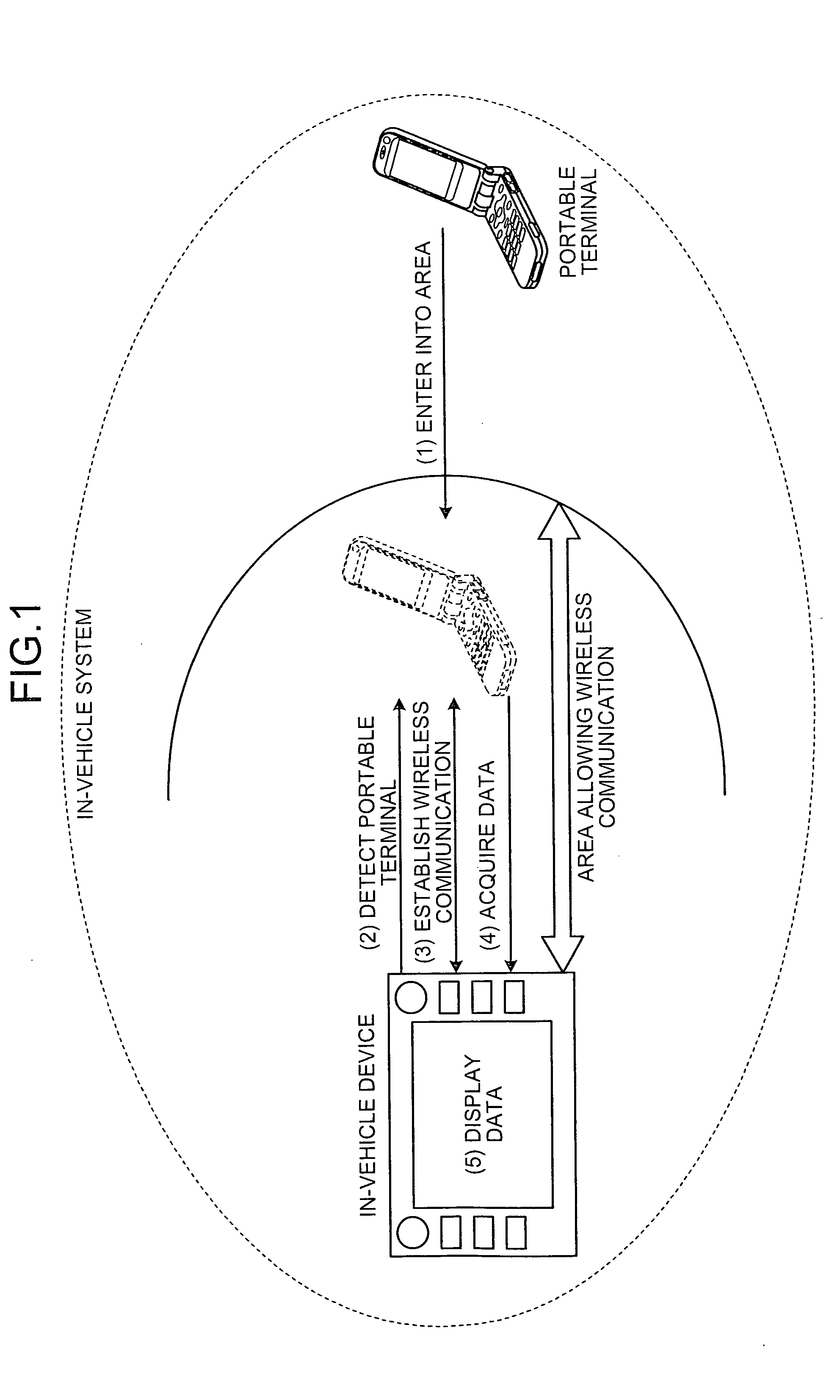
[0035]In this way, in the in-vehicle device when the in-vehicle device and the portable terminal are positioned at a distance allowing wireless communication, wireless communication is established automatically without any special operation by the user, and information of the portable terminal can be provided to the in-vehicle device. As a result, linkage between the portable terminal and the in-vehicle device can be easily controlled regardless of user's skills.

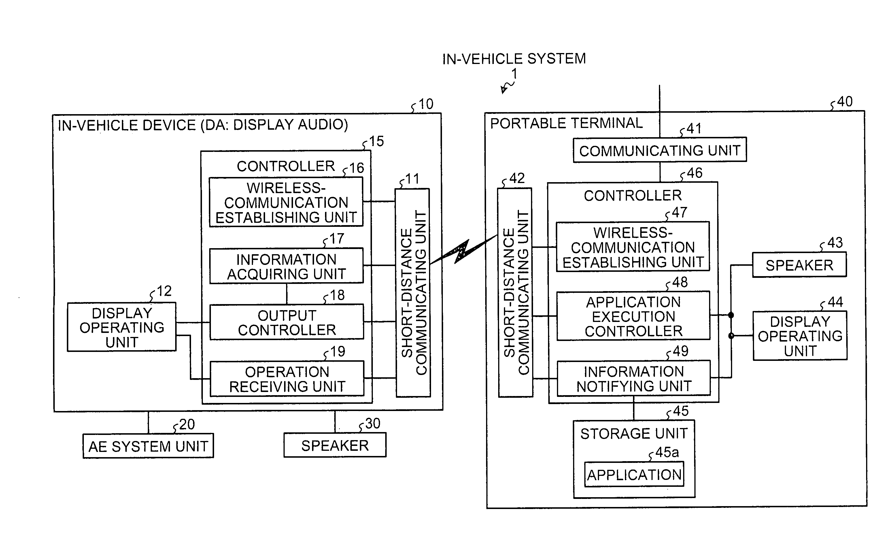
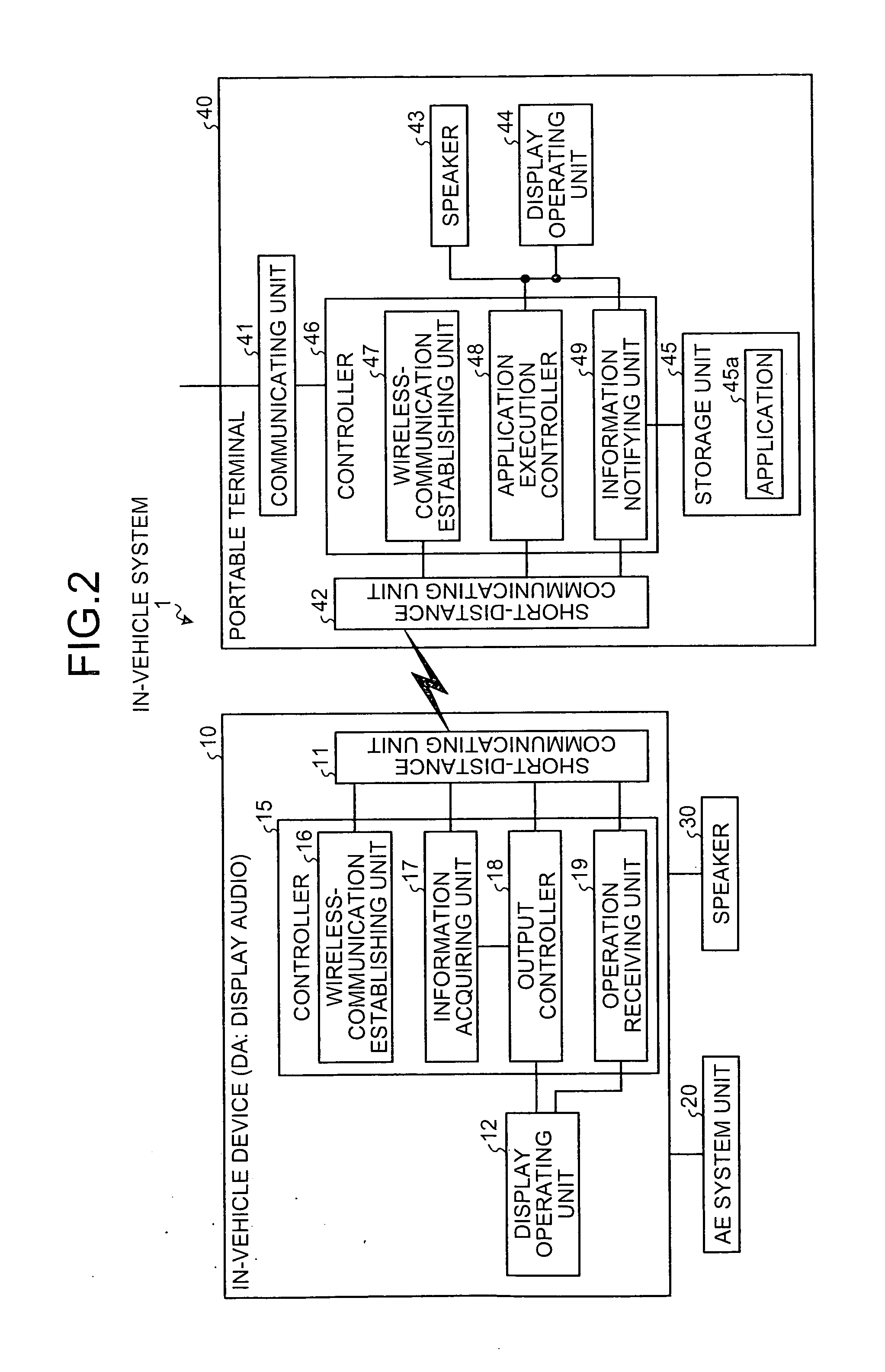
[0036]A configuration of the in-vehicle system shown in FIG. 1 is explained with reference to FIG. 2. FIG. 2 is a block diagram of the configuration of the in-vehicle system. As illustrated in FIG. 2, because an in-vehicle system 1 includes an in-vehicle device 10 and a portable terminal 40, the respective devices are explained.

[0037]A configuration of the in-vehicle device 10 in the in-vehicle system 1 is explained first. As illustrated in FIG. 2, the in-vehicle device 10 includes a short-distance communicating unit 11, a ...

fourth embodiment

[0095]As illustrated in FIG. 6, upon reception of a linkage termination instruction (for example, pressing of a linkage canceling button) by a user operation (YES at Step S401), the in-vehicle device 10 in the in-vehicle system 1 performs an exiting process depicted in FIG. 7 (Step S402).

[0096]Thereafter, the in-vehicle device 10 outputs a message (a caution) indicating linkage suspension from the display operating unit 12 and the speaker 30 (Step S403), and waits for a vehicle engine (ACC) to be turned off (YES at Step S404), to finish a linking process (Step S405).

[0097]On the other hand, returning to Step S401, when the linkage termination instruction by the user operation is not received (NO at Step S401), the in-vehicle device 10 determines whether the linkage termination instruction is given by turning off the vehicle engine (Step S406).

[0098]When the linkage termination instruction is given by turning off the vehicle engine (YES at Step S406), the in-vehicle device 10 perfor...


PUM


Abstract

Upon detection of a portable terminal positioned at a predetermined distance allowing wireless communication with an in-vehicle device, the in-vehicle device in an in-vehicle system performs a pairing process with respect to the detected portable terminal to establish wireless communication with the detected portable terminal. Thereafter, the in-vehicle device acquires an image and sound acquired by an application being executed on the portable terminal from the portable terminal, with which wireless communication has been established. The in-vehicle device converts acquired various types of data into an outputtable format of the in-vehicle device and outputs the converted data to at least one of a display unit and a speaker.

Description


Claims


Application Information

Patent Timeline
Owner FUJITSU GENERAL LTD
Why Eureka
Try Eureka