Multiple, pivotal non-coplanar tools

a multi-functional, non-coplanar technology, applied in the field of hand tools, can solve the problems of reducing affecting the use of hand tools, and affecting the safety of hand tools, so as to reduce the risk of musculoskeletal disorders and other injuries, reduce the amount of grip force that a person can apply to a hand tool, and avoid injury

Inactive Publication Date: 2010-06-10
ANDERSON WAYNE +1
View PDF0 Cites 5 Cited by
  • Summary
  • Abstract
  • Description
  • Claims
  • Application Information

AI Technical Summary

Benefits of technology

[0018]It is critical to the instant invention that the center of gravity of the instant device be substantially aligned with the user's hand and arm. As such, the desired tool implement of the instant device, when in the distended functional position, will be in-line with the gripping, extension and containment portion. Having the tool implement in-line with the gripping, extension and containment portion will allow the user's wrist posture to remain straight, so as to avoid injury. This is critical in that as the wrist posture deviates from the straight position, the amount of grip force that a person can apply to a hand tool decreases proportionally. Indeed, it is recognized that maintaining a user's hands and arms in alignment will reduce the risk of musculoskeletal disorders and other injury during even prolonged hand tool use.
[0019]The contour of the gripping, extension and containment portion of the instant device is large enough so as not to cause discomfort, and to help distribute forces on fingers. The contour of the gripping, extension and containment portion permits the even distribution of forces over the largest area of the hand possible.
[0020]Optimally, the gripping, extension and containment portion of the instant invention resides between 3.75 and 5 inches in length to extend across the entire breadth of the palm to allow the user to apply a power grip. Gripping, extension and containment portions larger than 4 inches will typically reduce the negative effects of any compression exerted. Additionally, the gripping, extension and containment portion resides in a diameter of between 1.25 to 2 inches, depending on the amount of torque required. The greater the torque required, the greater the diameter of the gripping, extension and containment portion.

Problems solved by technology

In order to meet this demand, a multiplicity of combined tool structures have been offered but do not carry the advantages or design of that set forth hereinbelow.
The subject matter disclosed in Elsener and Zirk however, fails to disclose a device in which the illumination is virtually in axis parallel with the tool and thus actually illuminating the tool, the object of work, and the work space involved.
Moreover, the above-referenced devices fail to provide a foldable hand tool which is ergonomically and functionally designed to conform with the hand of the user.
Therefore, users of hand tools, who are oft required to twist their arms, hands, and wrists repeatedly or forcefully are susceptible to musculoskeletal disorders.
Musculoskeletal disorders are often painful and are usually involve debilitating swelling.
Often one can associate the condition with the design (i.e., the device is awkward in holding and implementation) and with the inability to illuminate the working environment (often a flashlight is held in the mouth of the user to provide light to the working environment).

Method used


Image

  • Multiple, pivotal non-coplanar tools
  • Multiple, pivotal non-coplanar tools
  • Multiple, pivotal non-coplanar tools

Examples


Embodiment Construction

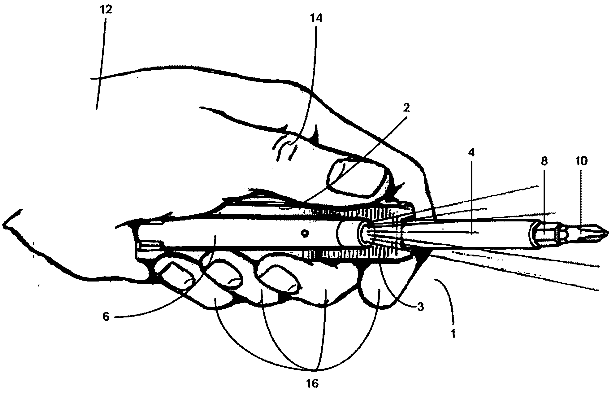
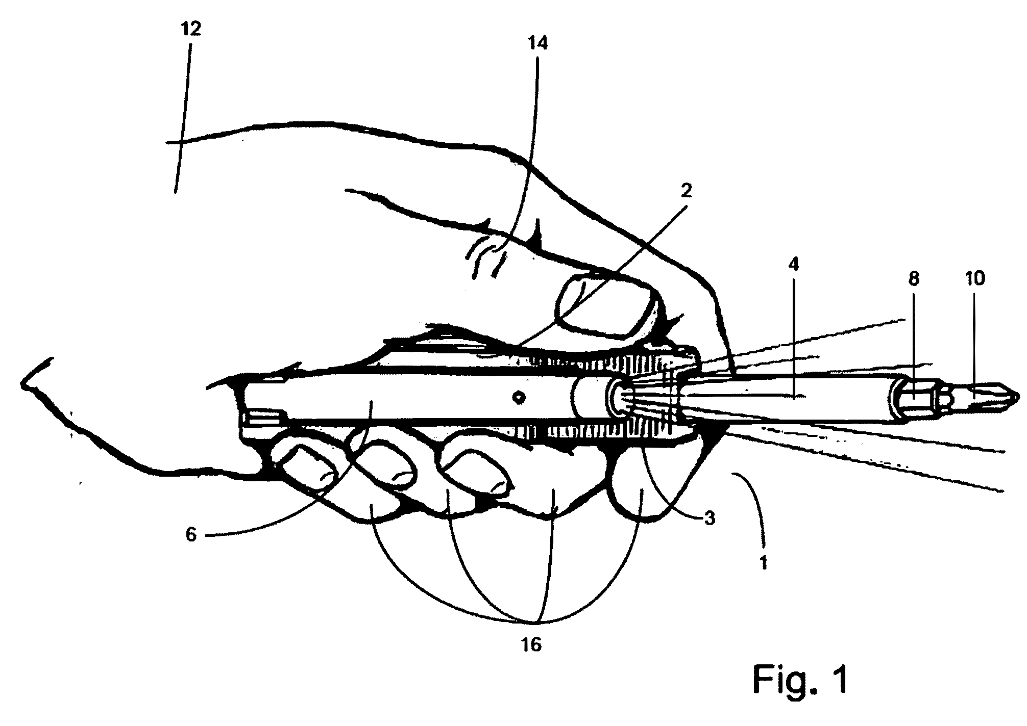
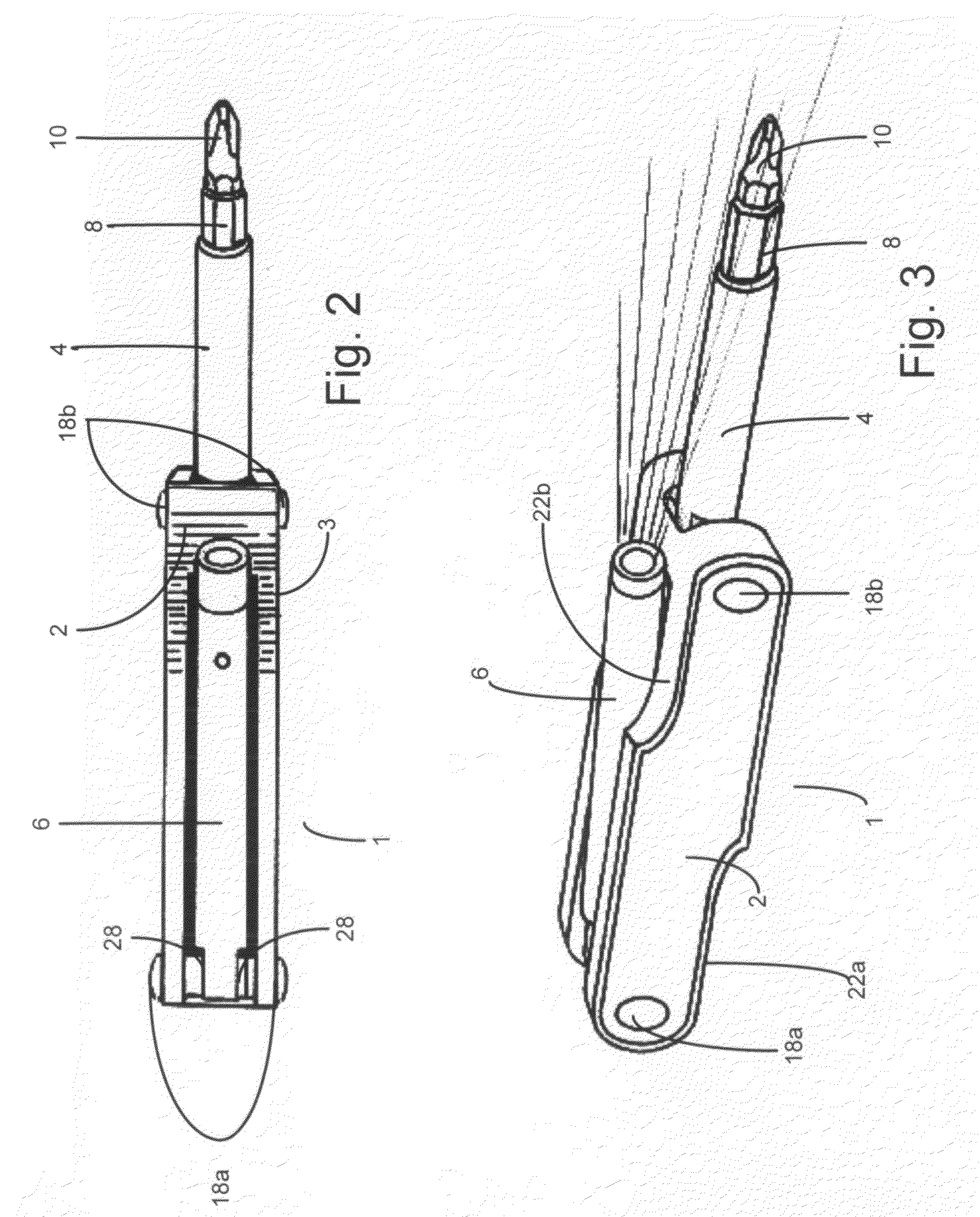
[0040]As shown in FIG. 1, the preferred embodiment of the present invention is directed to device 1 which permits the use of two tools simultaneously, in this case flashlight 6 and Phillips head 10. As shown, flashlight 6, in the stored functional position, can illuminate the tool means, in this instance a Phillips head 10, and the screw (not shown but understood to exist) to which it will engage, in a manner in which the illumination is virtually in parallel with the tool and thus actually creates light for the work space and the work involved. Such a combination is heretofore unknown.

[0041]Moreover, and in particular, hand 12 of a user engages by way of fingers 16, handle 2 of device 1 and via thumb 14, rests upon a textured thumb grip 3 of specific configuration to create a power gripping effect as discussed in greater detail hereinbelow. As a result of the dimensions, flashlight 6, folded in the stored position, as shown, is such that the entire device 1, save the tool means (co...


PUM


Abstract

A tool assembly primarily for illuminating a work space having a plurality of tools each of which having both a proximal and distal end for providing rotational movement of each of the tools for extension to at least one functional position and a distal end for use of the tool in the work space, and a stored position when not in use; in which one of said tools means is a flashlight means for illuminating at least the work space and at least one other said tools at the proximal end. The assembly further has a gripping, extension and containment portion within the assembly for engaging the tool and for providing pivotal positioning of the tools from the functional position through to the stored position; at least two non-vertically coplanar hinge pins for pivotal engagement of each of the tools from the stored position through the functional position; such that when the tools are pivoted to at least one aligned functional position the tools are substantially parallel and vertically coplanar and when the tools are pivoted to a stored position the tools are substantially contained within the assembly in a parallel, co-vertically planar arrangement by way of recesses in the said gripping, extension and containment portion; the gripping, extension and containment portion further has an arcuately sloped surface means for ergonomic and useful functioning, for wresting the flashlight or a thumb when in use.

Description

[0001]This is a divisional of U.S. Ser. No. 11 / 515,127, filed Sep. 1, 2006, from which priority is claimed. U.S. Ser. No. 11 / 515,127 was assigned to art unit 2885. U.S. Ser. No. 11 / 515,127 has been allowed for issuance as a patent. The U.S. Patent and Trademark Office classification of the instant divisional application is unknown.FIELD OF THE INVENTION[0002]The present invention relates to the field of hand tools and more particularly to ergonomically and functionally constructed hand tools for a plurality of uses that comprise pivotal extension axes that do not reside in the same horizontal plane and pivot from open, useable position(s), to a stored, closed position within the handle, including preferably a tool flashlight that while foldable is also positionable virtually parallel to the axis of the tool and illuminates the tool and its use in the worksite.BACKGROUND OF THE INVENTION[0003]The instant invention relates to an ergonomically and functionally designed foldable hand to...

Claims


Application Information

Patent Timeline
Patent Type & Authority Applications(United States)
IPC IPC(8): B25F1/04B25B23/18
CPCB25B23/18B26B11/008B25G1/102B25F1/04
Inventor ANDERSON, WAYNEANDERSON, WARREN
Owner ANDERSON WAYNE
Why Eureka
Try Eureka