Clip for wig

a technology for wigs and clips, applied in the field of clips for wigs, can solve the problems that the exposure of wigs cannot be prevented, and achieve the effect of avoiding the exposure of wearing wigs

Active Publication Date: 2010-06-10
ADERANS CO LTD
View PDF7 Cites 12 Cited by
  • Summary
  • Abstract
  • Description
  • Claims
  • Application Information

AI Technical Summary

Benefits of technology

[0014]The clip of the present invention for a wig can be attached to the wig base so as to coincide with the curved shape of the periphery of the wig base because the outer shape of the reversible member is formed in circular arc. Especially, by using the clip of the present invention for a wig, since the outer shape of the reversible member is curved with the curvature of the same level as that of the curved periphery, that is, the turn back portion swelling outward from the forehead hairline corners toward the sideburns backward at the side head portions of the wig base, and hence it can be attached only slightly inside along said turn back portion, the protruding portion from the clip for a wig to the periphery of the wig base can be made smaller than the conventional clip for a wig as shown in FIG. 31. Therefore, the warping of the wig can be prevented to occur, and the exposure of wearing a wig can be avoided.

Problems solved by technology

However, since the shape of the periphery of the swollen portion S3 of the wig base 30 does not coincide with the shape of the outer frame of the clip 100 for a wig, the area of the protruding portion from the clip 100 for a wig to the periphery of the wig base 30 can not help but become large, this protruding portion easily warping, and hence possibility of exposure of the wig can not be prevented.

Method used


Image

  • Clip for wig
  • Clip for wig
  • Clip for wig

Examples


embodiment 1

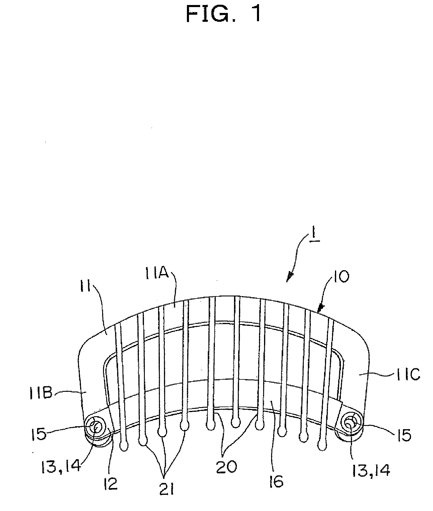
[0047]FIG. 1 illustrates the clip 1 of the present invention for a wig in this first embodiment. Said clip 1 for a wig is constituted with a reversible member 10 and a plurality of linear comb teeth 20 attached to said reversible member. The reversible member 10 is made of an elastically deformable metallic thin plate to frame-shaped, and the comb teeth 20 are made of elastically deformable metallic thin wires or rods.

[0048]The reversible member 10 is constituted with an U-shaped frame member 11, the original Japanese language reads “” which is a Japanese katakana letter “ko”, having leg portions 11B and 11C protruding from both ends of a belt-like support portion 11A in the same direction to make a right angle to the support portion 11A in the same plane and a belt-like connecting portion 12 connected to each of leg portions 11B and 11C of said U-shaped frame member 11.

[0049]A connecting hole 13 is provided to the each tip of leg portions 11B and 11C of the U-shaped frame member 11...

embodiment 2

[0082]The clip for a wig of the second embodiment of the present invention is explained next.

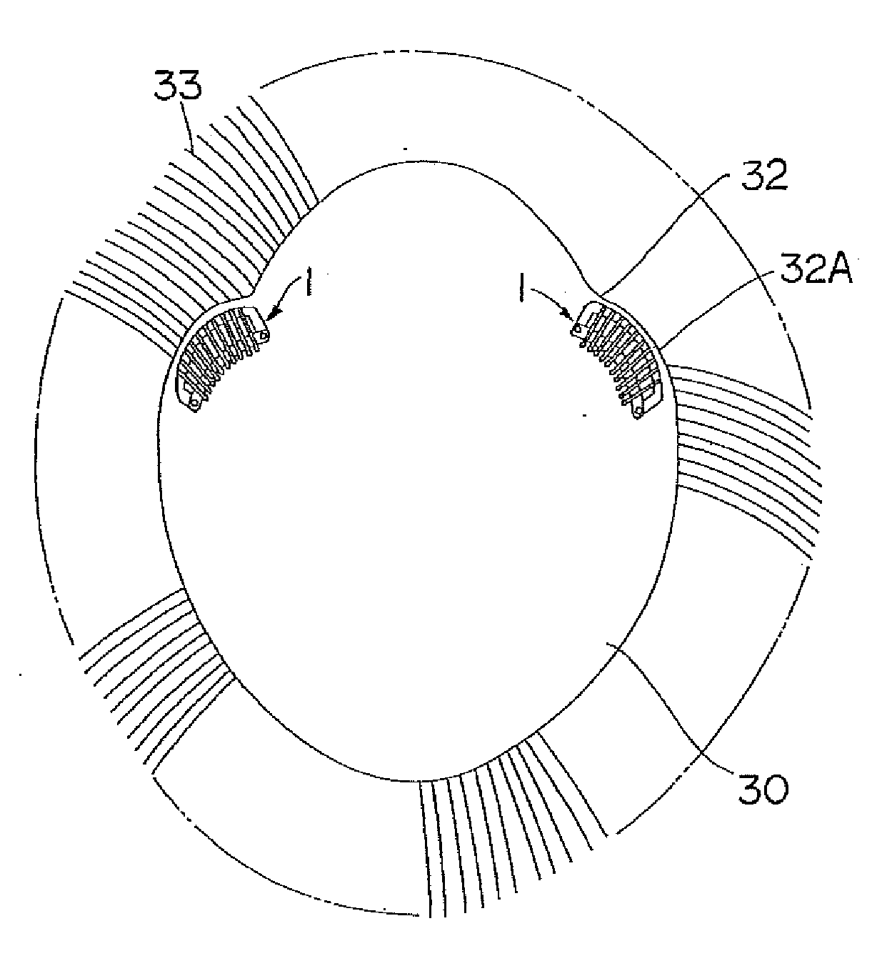
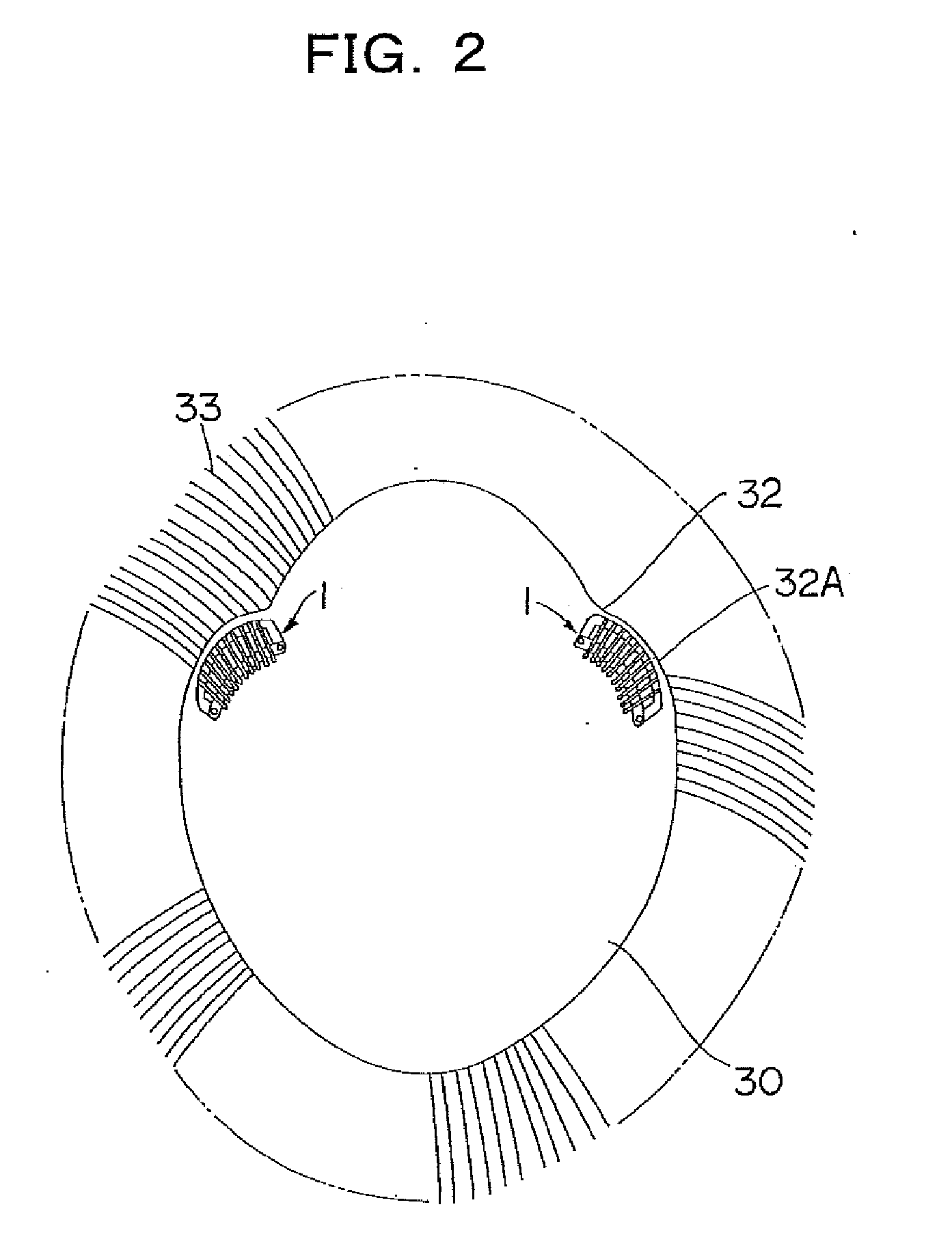
[0083]FIG. 17 illustrates the clip for a wig of the second embodiment, and the clip 2 for a wig of the present embodiment is characterized to be attached to a wig base 30 via a sheet. Here, the same constituent members as in the clip 1 for a wig of the embodiment 1 are numbered with identical numbers, and the details of its explanation are omitted.

[0084]The clip 2 for a wig in accordance with the present embodiment is provided with penetration holes 18 for attaching the sheet to respective leg portions 11B and 11C of the reversible member 10, and such connecting pieces as metal eyelets and rivets are inserted to said penetration holes 18, thereby the sheet is attached to the clip 2 for a wig.

[0085]FIG. 18 illustrates the state of a sheet 35 attached to the clip 2 for a wig of the present embodiment, and FIG. 19 is the diagnosis drawing of FIG. 18. As shown in these figures, the sheet 35 is a...


PUM


Abstract

A clip for wig is offered which can prevent warping of a wig base.The clip 1 for wig is constituted with a frame-like reversible member 10 and a plurality of comb teeth 20 attached to the reversible member 10, the reversible member 10 is constituted with an U-shaped frame material 11 having leg portions 11B and 11C protruding from both ends of a support portion 11A and a connecting portion 12 connected to respective leg portions 11B and 11C of the U-shaped frame material 11, a plurality of comb teeth 20 are fixed at the end portion of the support portion 11A of the U-shaped frame material 11, the outer shape of the support portion 11A is formed to have a curvature of the circular arc along the curved periphery of the wig base 30, and the support portion of the clip 1 of a wig is provided at the position close to the periphery, thereby to be fixed to the reverse side of the wig base.

Description

TECHNICAL FIELD[0001]The present invention relates to a clip for a wig used for fixing a wig to a wearer's head, and especially to a clip for a wig used by fixing it to the reverse side of a wig base along its curved periphery remarkably swelling from the hairline corner of the forehead of the wig base, and to the wig provided with said clip.BACKGROUND ART[0002]A clip for a wig is used by being attached to the reverse side of a wig base with numerous hair planted thereto, for fixing a wig to the head by clipping to the wearer's own hair around a thin hair portion.[0003]For example, as shown in FIG. 30, a conventional clip 100 for a wig is constituted with a reversible member 110 and a plurality of comb teeth 120 protruding needle-like held at an end and attached to said reversible member 110. The reversible member 110 can maintain the warping posture, and by reversing alternatively the warping direction, the tips of the comb teeth 120 can be firmly attached to, or detached from, the...

Claims


Application Information

Patent Timeline
Patent Type & Authority Applications(United States)
IPC IPC(8): A45D8/38A41G3/00
CPCA41G3/0033A41G3/005
Inventor UMEZU, KAZUHIROSASAKI, YOSHIMIMATSUDA, TETSUHIRO
Owner ADERANS CO LTD
Why Eureka
Try Eureka