Kinetic energy vehicle

Active Publication Date: 2010-06-10
CENT RECREATION SUPPLY
View PDF3 Cites 13 Cited by
  • Summary
  • Abstract
  • Description
  • Claims
  • Application Information

AI Technical Summary

Benefits of technology

[0020]It is another object of the present invention to provide a new and improved kinetic energy vehicle which may be easily and efficiently manufactured and marketed.
[0021]It is further object of the present invention to provide a new and improved kinetic energy vehicle which is of durable and reliable constructions.
[0022]An even further object of the present invention is to provide a new and improved kinetic energy vehicle which is susceptible of a low cost of manufact

Problems solved by technology

While prior art devices fulfill their respective, particular objectives and requirements, they do not describe a kinetic energy vehicle that allows for u

Method used


Image

  • Kinetic energy vehicle
  • Kinetic energy vehicle
  • Kinetic energy vehicle

Examples


Example

[0042]The same reference numerals refer to the same parts throughout the various Figures.

DESCRIPTION OF THE PREFERRED EMBODIMENT

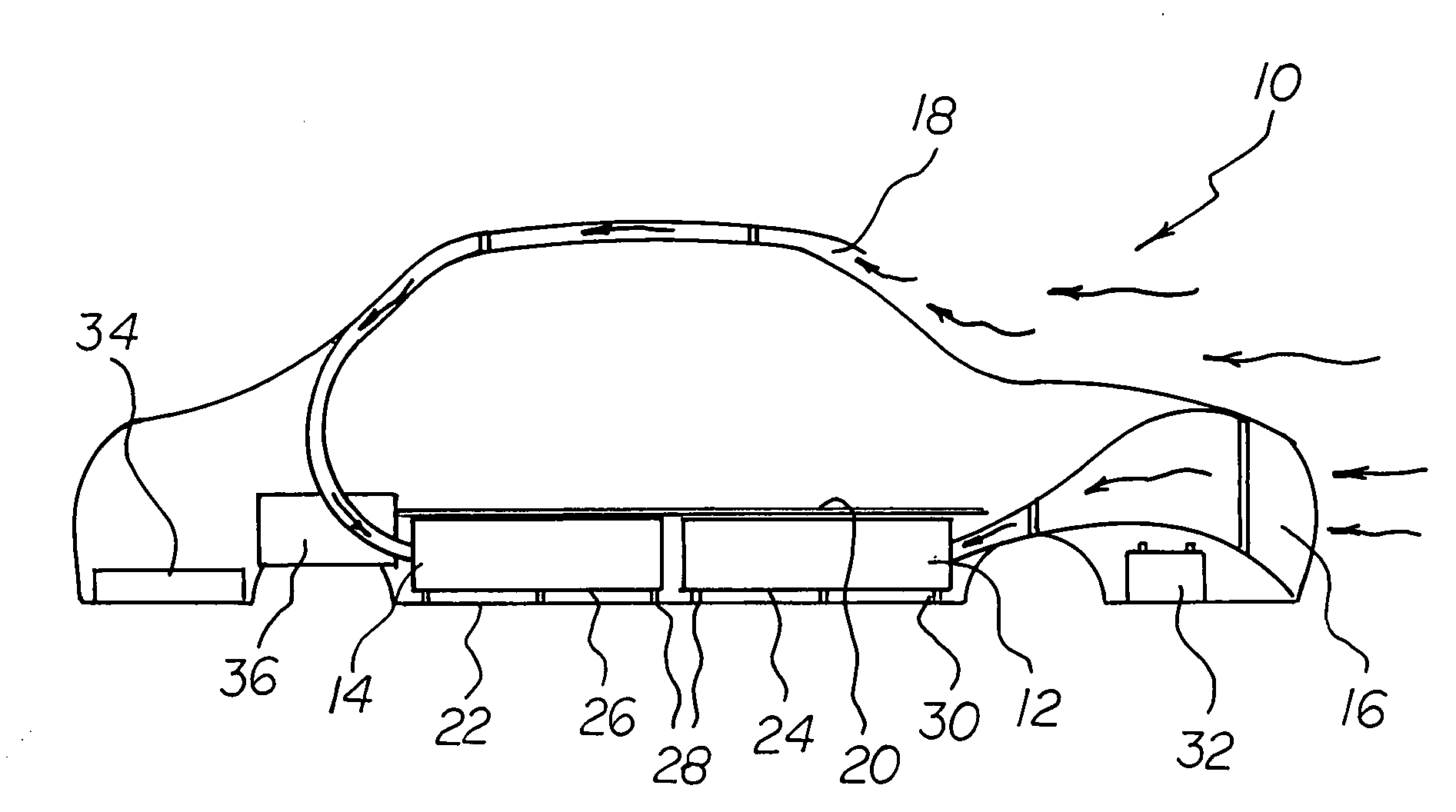
[0043]With reference now to the drawings, and in particular to FIG. 1 thereof, the preferred embodiment of the new and improved kinetic energy vehicle embodying the principles and concepts of the present invention and generally designated by the reference numeral 10 will be described.

[0044]The present invention, the kinetic energy vehicle 10 is comprised of a plurality of components. Such components in their broadest context include a main body portion, a housing in the vehicle containing a turbine / flywheel, a starter generator in the housing, a main drive generator, and an electric drive motor. Such components are individually configured and correlated with respect to each other so as to attain the desired objective.

[0045]FIG. 1 is a side elevational view of a vehicle 10 showing the location of the turbines 12, 14 and the air flows through the vehicle to t...


PUM


Abstract

A main body portion has a front, a rear, a top, a bottom and laterally spaced sides and an air intake. A housing in the vehicle contains a turbine/flywheel adapted to be rotated in response to air entering the housing from the air intake. A starter generator in the housing is adapted to be rotated by the rotation of the turbine/flywheel. A main drive generator in the housing is adapted to be rotated by the rotation of the turbine/flywheel. An electric drive motor in the vehicle is powered from the main drive generator.

Description

BACKGROUND OF THE INVENTION[0001]1. Field of the Invention[0002]The present invention relates to a kinetic energy vehicle and more particularly pertains to utilizing wind to counter rotate turbines in a vehicle when moving for powering the vehicle in a safe, energy efficient, economical and ecological manner.[0003]2. Description of the Prior Art[0004]The use of kinetic energy vehicles of known designs and configurations is known in the prior art. More specifically, kinetic energy vehicles of known designs and configurations previously devised and utilized for the purpose of efficiently powering vehicles are known to consist basically of familiar, expected, and obvious structural configurations, notwithstanding the myriad of designs encompassed by the crowded prior art which has been developed for the fulfillment of countless objectives and requirements.[0005]While prior art devices fulfill their respective, particular objectives and requirements, they do not describe a kinetic energ...

Claims


Application Information

Patent Timeline
IPC IPC(8): B60L8/00
CPCB60K16/00B60K2016/006F03D9/002Y02E10/725Y02T10/7083Y02T10/90B60L8/006F05B2240/941F03D9/12F03D9/25F03D9/32F03D15/20F03D80/70Y02E10/72Y02E10/728Y02E60/16Y02E70/30Y02T10/7072
Inventor FRIERMAN, EDWARD MICHAEL
Owner CENT RECREATION SUPPLY
Why Eureka
Try Eureka