Hydraulic shock absorber

a technology of shock absorber and axial length, which is applied in the direction of shock absorbers, mechanical equipment, transportation and packaging, etc., can solve the problems of large axial length of shock absorbers, complicated configurations for pressure-application, and water ingress into the shock absorber, so as to achieve a simple and miniaturized structure, and maintain the constant oil amount in the piston chamber

Active Publication Date: 2010-06-10
SMC CORP
View PDF8 Cites 17 Cited by
  • Summary
  • Abstract
  • Description
  • Claims
  • Application Information

AI Technical Summary

Benefits of technology

[0014]According to the present invention, a hydraulic shock absorber with a simple and miniaturized structure, capable o

Problems solved by technology

As a result, generally, shock-absorbing capacity as the shock absorber lowers while the oil amount in the piston chamber is gradually reduced, and thus the hydraulic shock absorber comes to the end of its life.
For this reason, not only the co

Method used


Image

  • Hydraulic shock absorber
  • Hydraulic shock absorber

Examples


Embodiment Construction

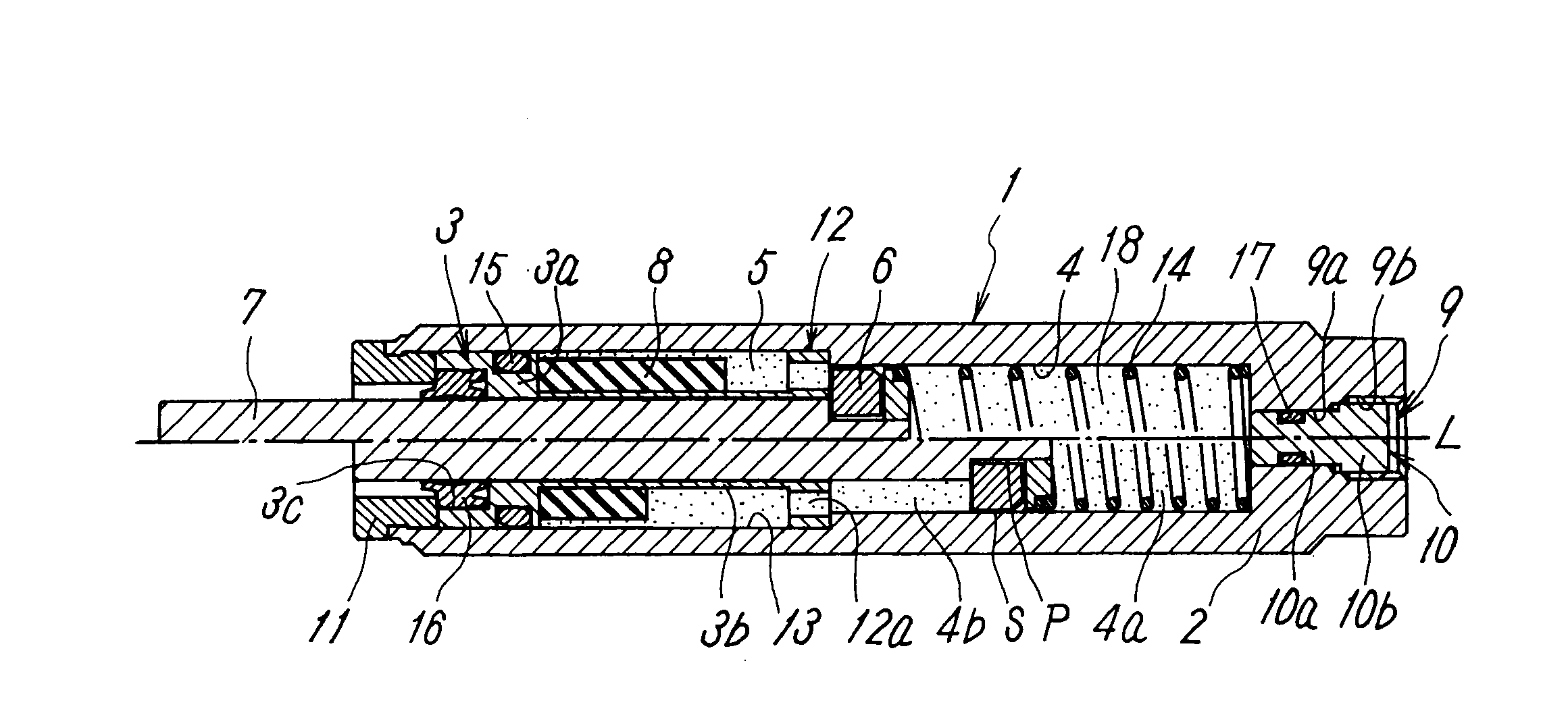
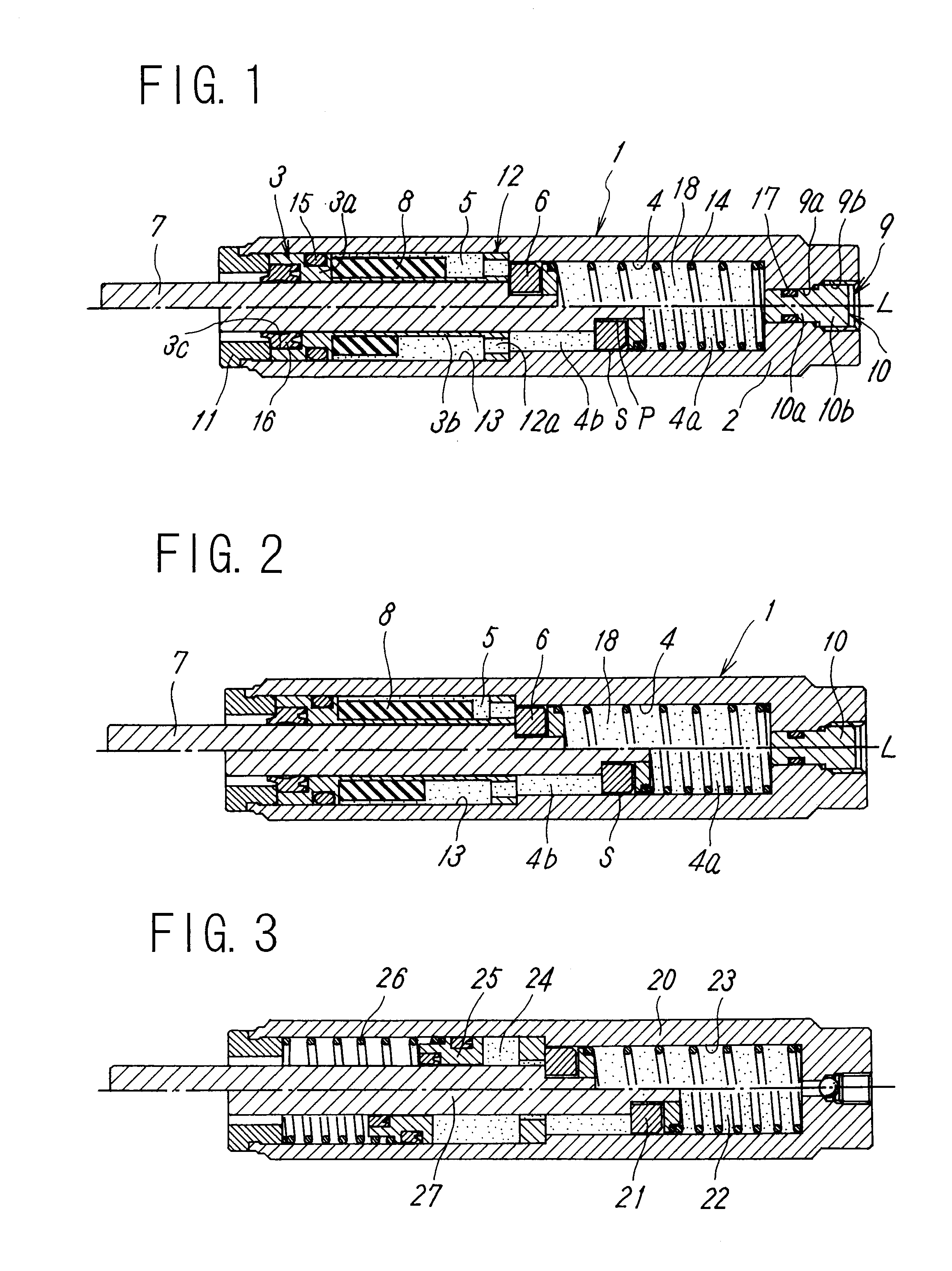
[0040]FIGS. 1 and 2 show one embodiment of a hydraulic shock absorber according to the present invention. The shock absorber has a cylindrical-shaped cylinder tube 1. The cylinder tube 1 has a first end wall 2 located at a proximal end side in a direction of an axial line L, a second end wall 3 located at a leading end side, and an intermediate wall 12 located in its mid-position. In addition, the cylinder tube 1 includes, in its inside, a piston chamber 4 and an adjustment chamber 13 which are formed between the intermediate wall 12 and the first end wall 2 and between the intermediate wall 12 and the second end wall 3, respectively, so as to mutually communicate through a communicating part 12a of the intermediate wall 12; oil 18 filling the piston chamber 4 and the adjustment chamber 13 in the pressurized state; a shock-absorbing piston 6 which moves in the direction of the axial line L in the inside of the piston chamber 4; a rod 7 mounted on the piston 6, a leading end of which...


PUM


Abstract

In the inside of a cylinder tube, there are provided a piston chamber and an adjusting chamber communicating each other, and these both chambers are filled with oil in a pressurized condition, and further, there are provided a piston moving in an axial direction in the piston chamber and a rod coupled to the piston. An elastic member is located in the inside of the adjusting chamber in a state that a reservoir tank is formed in the adjusting chamber by being compressed by pressurizing force of the oil, and impact is absorbed in such a way that the elastic member is caused to extend and contract by the oil flowing in/flowing out the reservoir tank by movement of the rod.

Description

TECHNICAL FIELD[0001]The present invention relates to a hydraulic shock absorber absorbing an impact when a moving object is stopped while utilizing a flow resistance of oil.BACKGROUND ART[0002]A hydraulic shock absorber, for example, as described in Patent Document, Japanese Patent Application Laid-Open No. 2006-250309, has a configuration in which a piston chamber of a cylinder tube is filled with oil such as mineral oil and a braking piston is accommodated in the piston chamber in a state that a communication gap of the oil is kept at an outer periphery of the piston, and a rod connected to the piston is extended outward from the cylinder tube. Then, kinetic energy of the moving object is absorbed by flow resistance of the oil flowing through the communication gap when the piston shifts by collision of the moving object at the leading end of the rod.[0003]The rod, which is always urged by a restoration spring toward an initial position, repeats an operation of advancing to the in...

Claims


Application Information

Patent Timeline
IPC IPC(8): F16F9/49
CPCF16F9/19F16F9/003F16F9/32F16F9/00
Inventor MIYASATO, EIKO
Owner SMC CORP
Why Eureka
Try Eureka