
Rotation compensation device
A technology of rotation compensation and rotating components, which is applied in projection devices, printing devices, televisions, etc., can solve problems such as image incongruity, and achieve the effects of reduced stack height, ingenious structural design, simple structure and miniaturization
- Summary
- Abstract
- Description
- Claims
- Application Information
AI Technical Summary
Problems solved by technology
Method used
Image

Examples
Embodiment Construction
[0024] The following is attached with the manual Figure 1-Figure 8 The present invention is described in further detail.
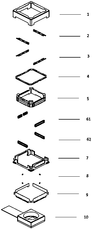
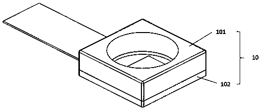
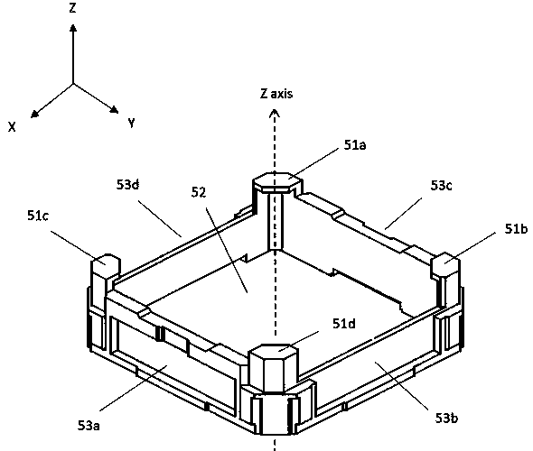
[0025] Such as Figure 1-Figure 8 As shown, the rotation compensating device includes a base 7, a carrier 5 carrying an optical path adjustment element 10, a substrate 9 connected to the optical path adjustment element 10, and a housing 1 arranged outside the base 7. The outer periphery of the carrier 5 is surrounded by a plurality of Axial rotating bracket 4, a pair of rotating elements are respectively fixed between the multi-axis rotating bracket 4 and the carrier 5, between the base 7 and the multi-axis rotating bracket 4, respectively the first rotating element 2 and the second rotating element 3, two pairs of rotating The elements are arranged perpendicular to each other. The rotating element has an inner connecting part, an outer connecting part, and a rotating shaft co-directional connecting body connected between the inner and outer connecting ...
PUM
 Abstract
Description
Claims
Application Information