Simplified rotating module

A technology of rotating modules and rotating shafts, which is applied to TVs, color TV parts, electrical components, etc. It can solve the problems of large volume of kits, electrical signal introduction, and multiple parts of multiple kits, so as to reduce complexity and difficulty. , Miniaturized structure and simple structure

Pending Publication Date: 2021-05-07
辽宁中蓝光电科技有限公司
View PDF0 Cites 0 Cited by
  • Summary
  • Abstract
  • Description
  • Claims
  • Application Information

AI Technical Summary

Problems solved by technology

However, the use of two sets of kits has the following problems: 1. The kits take up a large volume, which leads to difficulties in stack design; 2. It is difficult to import electrical signals into multiple kits, and the sensing of the inner kit is easily interfered by the rotation of the outer kit, resulting in signal crosstalk. ; 3. There are many parts in multiple kits and the cost is high, and the assembly process is complicated

Method used


Image

  • Simplified rotating module
  • Simplified rotating module
  • Simplified rotating module

Examples


Embodiment 1

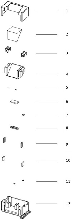
[0035] Such as figure 1 As shown, the simplified rotary module includes: a housing 1; a bearing seat 4 for carrying the optical path adjustment assembly 2 for adjusting the angle of the optical path. In this embodiment, the optical path adjustment assembly 2 is a prism, and the upper surface of the bearing seat 4 is provided with There are grooves corresponding to the prism; a base 12 forms an accommodating space with the housing 1 for containing and supporting the bearing seat 4, and has a rotation avoidance space for the bearing seat 4; a supporting component 5 is arranged between the bearing seat 4 and the base 12. Satisfy and limit the rotation of the bearing seat 4 around the first rotation axis and the second rotation axis respectively, and the first rotation axis and the second rotation axis are perpendicular to each other; a clamping assembly 3 is arranged between the bearing base 4 and the base 12 , providing a clamping force to keep the bearing seat 4, the base 12 an...

Embodiment 2

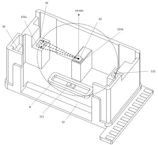
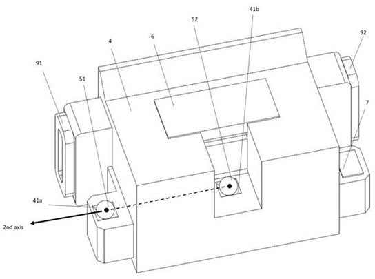
[0049] Such as Figure 7 , Figure 8 As shown, the difference between this simplified rotary module and Embodiment 1 is that two arc-shaped tracks 1211a, 1211b corresponding to the balls 51, 52 are arranged on the base 12, and the virtual centers of the two arc-shaped tracks 1211a, 1211b overlap, and the bearing seat 4 Accommodating point grooves 43a, 43b corresponding to the two balls 51, 52 are provided on the top. In this embodiment, the first rotation axis is perpendicular to the plane where the two arc-shaped tracks 1211a, 1211b are located and passes through the virtual center of the arc-shaped tracks 1211a, 1211b, and the second rotation axis is the center of the two balls 51, 52. virtual connection. When the electromagnetic rotational driving force acts on the bearing seat 4, the balls 51, 52 move clockwise or counterclockwise along the corresponding arc-shaped tracks 1211a, 1211b, and the bearing seat 4 rotates with the first rotation axis passing through the virtua...


PUM


Abstract

The invention relates to a simplified rotating module, and the module is characterized by comprising a housing, a bearing seat used for bearing the light path adjusting assembly, a base used for containing and supporting the bearing seat, a supporting assembly arranged between the bearing seat and the base and meeting and limiting the bearing seat to rotate around the first rotating shaft and the second rotating shaft respectively, a clamping assembly arranged between the bearing seat and the base and providing a clamping force to enable the bearing seat, the base and the supporting assembly to keep stable contact, a driving assembly used for generating driving force to enable the bearing seat to rotate around the first rotating shaft or the second rotating shaft, and a sensing assembly adopting an electromagnetic sensing assembly or an optical sensing assembly and used for measuring the rotating angles of the bearing seat on the first rotating shaft and the second rotating shaft. According to the invention, the rotating fulcrum and the arc-shaped track are matched with the clamping force, so that the two-axis rotation of one bearing seat can be realized without the assistance of additional suites, the requirement on the angle adjustment of the light path is further met, and the closed-loop control of the light path adjustment is realized by matching with the driving assembly and the sensing assembly.

Description

technical field [0001] The invention relates to a simplified rotating module, which is suitable for mounting an optical refraction module, and can also be extended to mount an optical lens or other optical components. Background technique [0002] Generally speaking, most of the voice coil motors on the market move in a straight line. Whether it is the focus motor (AF) or the anti-shake system motor (OIS), most of them are used to carry optical components for translation to achieve the required optical effect. Limited by the volume and height requirements of digital products on the market, linear optical path products need to be turned to reduce the size of the original equipment or components, that is, the turning of the optical axis is realized through the principle of refraction, thereby reducing the size of the initial equipment or components . In this case, the translational movement of the optical component may not be able to meet the optical path adjustment or applic...

Claims


Application Information

Patent Timeline
Patent Type & Authority Applications(China)
IPC IPC(8): H04N5/225
CPCH04N23/54H04N23/55
Inventor 游证凯许乃文宋秉儒
Owner 辽宁中蓝光电科技有限公司
Why Eureka
Try Eureka