
System for converting tidal wave energy into electric energy

Active Publication Date: 2010-06-10
ANDUJAR JUAN
View PDF21 Cites 16 Cited by
  • Summary
  • Abstract
  • Description
  • Claims
  • Application Information

AI Technical Summary

Benefits of technology

[0007]The invention provides a system for converting marine surface wave energy into electric energy. The system includes a barrier disposed generally vertically and having at least a portion thereof disposed above a surface of the body of water. The portion has a substantially planar surface disposed substantially transverse to direction of marine surface waves. There is a predetermined plurality of spaced apart pylons at least partially disposed in a vertical direction within the floor bed and aligned in a first linear pattern substantially transverse to direction of marine surface waves. There is also a predetermined plurality of elongated members. Each of the predetermined plurality of elongated members has each of a hollow interior and one end thereof disposed on and secured to the bottom edge of the barrier. A hinge assembly pivotally connects an opposed end of the each of the predetermined plurality of elongated members to an exposed end of a respective one of the predetermined plurality of first pylons. A predetermined plurality of elongated chambers disposed within the barrier. Each of the predetermined plurality of elongated chambers having a longitudinal axis thereof aligned in a vertical direction. There is a predetermined plurality of first electric generators. Each of the predetermined plurality of first electric generators is mounted within a respective elongated chamber and is coupled to storage of electric energy. Each of the predetermined plurality of first electric generators has a stator mounted for a rotational movement. There is also means for imparting the rotational movement of the stator. A predetermined plurality of first air passages formed through a top end of a respective one of the predetermined plurality of first electric generators. A predetermined plurality of second air

Problems solved by technology

Many present devices and systems employed to produce electricity emit fumes and chemicals which pose hazards to the ozone layer of the earth.
Furthermore, rising energy costs have affected not only businesses, but homeowners as well.

Method used


Image

  • System for converting tidal wave energy into electric energy
  • System for converting tidal wave energy into electric energy
  • System for converting tidal wave energy into electric energy

Examples


Embodiment Construction

[0033]Prior to proceeding to the more detailed description of the present invention, it should be noted that, for the sake of clarity and understanding, identical components which have identical functions have been identified with identical reference numerals throughout the several views illustrated in the drawing figures.

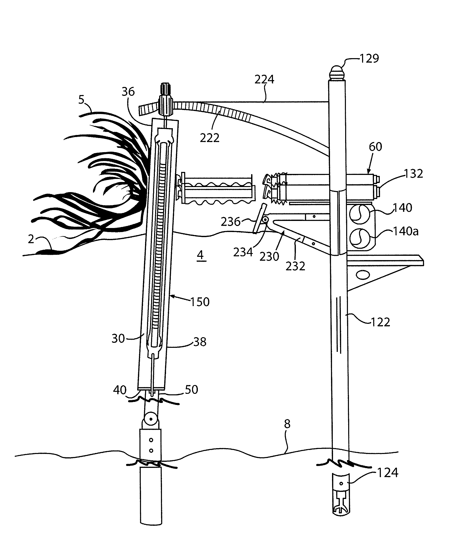
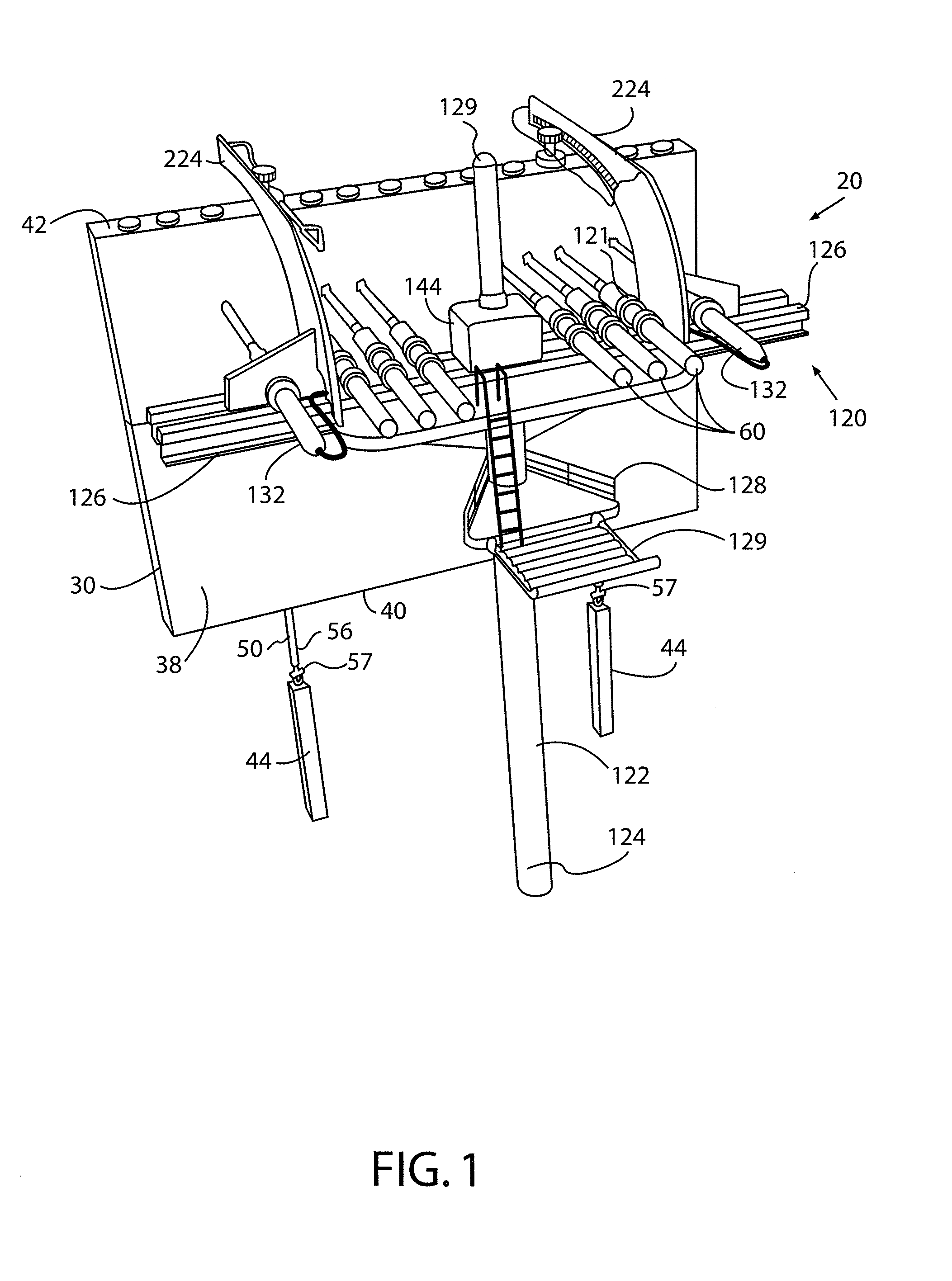
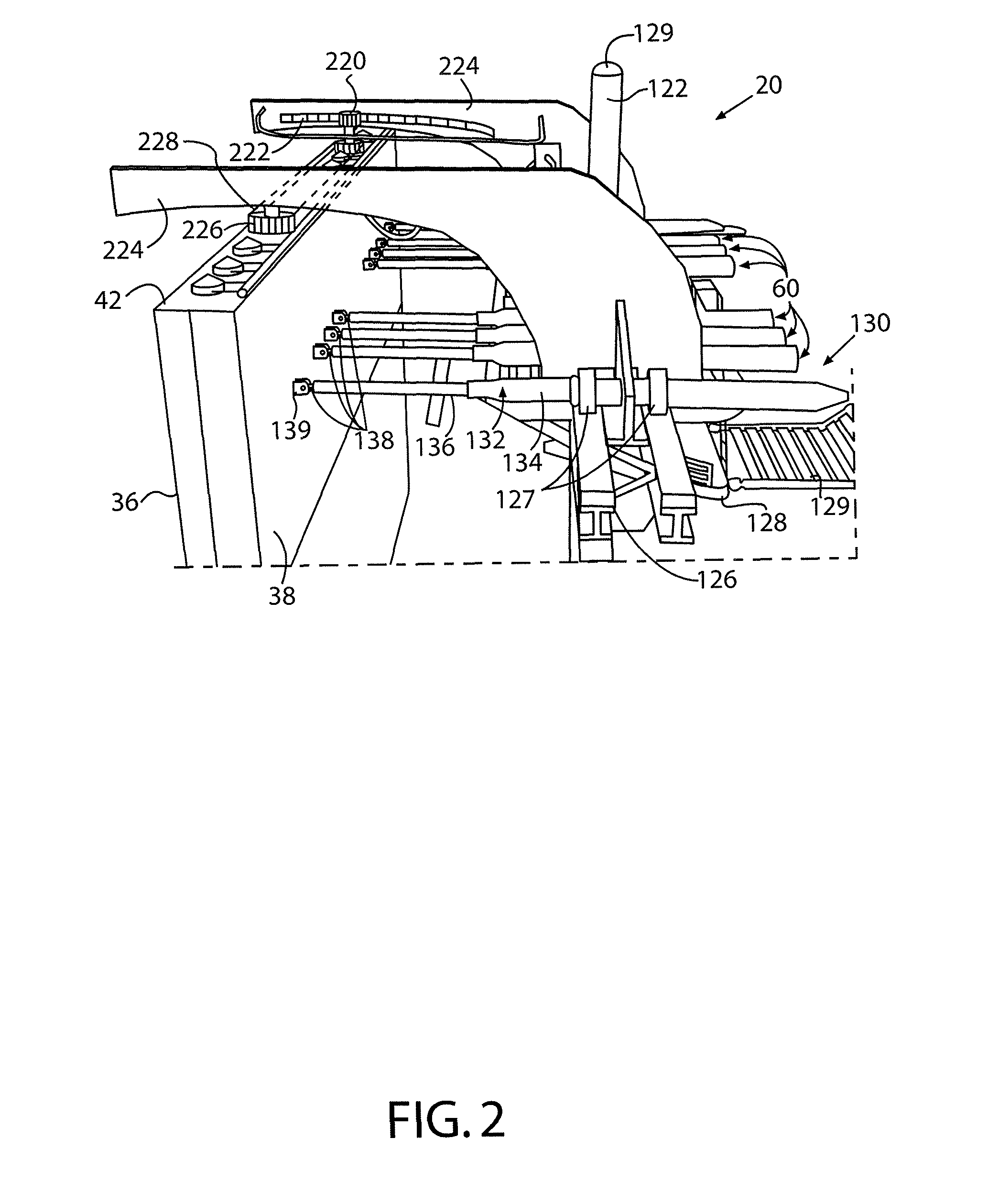
[0034]Now in reference to FIGS. 1-18, therein is provided a system, generally designated as 20, for converting energy of tidal waves 5 into electric energy. Such tidal waves 5, as is generally known, are present on a surface 4 of a large body of water 2. The surface 4 is generally meant to be defined as a mean low waterline.

[0035]A first essential element of the system 20 is a barrier 30 which is disposed generally vertically and has each of a lower portion 32 thereof submerged in a body of water 2 and an upper portion 34 thereof disposed above the surface 4 of the body of water 2. However, it is contemplated that the entire barrier 30 may be positioned above the s...


PUM


Abstract

A system for converting marine surface wave energy into electric energy includes a barrier disposed generally vertically and having at least a portion thereof disposed above a surface of a body of water. The portion has a substantially planar surface disposed generally transverse to direction of marine surface waves. Bottom edge of the barrier is pivotally connected to one of a floor bed, a rigid formation and a rigid structure. At least one linear electric generator is coupled to storage of electric energy and is operable by a pivotal movement of the barrier. One type of electric generator is disposed external to the barrier while another type is mounted within a barrier chamber.

Description

CROSS-REFERENCE TO RELATED APPLICATIONS[0001]This application is related to and claims priority from Provisional Patent Application Ser. No. 61 / 121,247 filed on Dec. 10, 2008 and from Provisional Patent Application Ser. No. 61 / 121,251 filed on Dec. 10, 2008.FIELD OF THE INVENTION[0002]The present invention relates, in general, to wave energy conversion systems and, more particularly, this invention relates to a system for converting tidal wave energy into electric energy and, yet more particularly, the instant invention is related to a system for converting tidal wave energy into electric energy that employs a rigid barrier submerged in a body of water and pivotally mounted to a floor bed and electric generators operable by barrier's pivotal movement caused by tidal waves.BACKGROUND OF THE INVENTION[0003]As is generally well known, carbon emissions from burning fossil fuels and reliance on foreign fuel sources are becoming increasing concerns for humanity. Many present devices and s...

Claims


Application Information

Patent Timeline
IPC IPC(8): F03B13/18H02K35/02H02K21/14
CPCF03B13/182F05B2220/706F05B2220/707Y02E10/38F05B2260/406H02K7/1876F05B2260/4031Y02E10/30
Inventor ANDUJAR, JUAN
Owner ANDUJAR JUAN
Learn More