Display Apparatus And Display System

a technology of display apparatus and display system, which is applied in the direction of identification means, instruments, cooling/ventilation/heating modifications, etc., can solve the problems of not being taken, difficult to place the liquid crystal display outdoors permanently, and difficult to cool the panel in the course of operation

Inactive Publication Date: 2010-06-10
SANYO ELECTRIC CO LTD
View PDF3 Cites 17 Cited by
  • Summary
  • Abstract
  • Description
  • Claims
  • Application Information

AI Technical Summary

Problems solved by technology

However, most of the conventional liquid crystal displays are designed for indoor installation, and consequently measures to protect them from environmental conditions such as a rainstorm, dust, snow, etc. are not taken.
Therefore, it is difficult to place the liquid crystal display outdoors permanently.
However, if a display panel is arranged inside the accommodation space, heat cannot escape outside, so it is difficult to cool the panel in the course of operation.
Therefore, the temperature of the panel may rise because of driving electric current, or may rise by the effect of exposure to sunlight.
As a result, it may not be possible to display a picture (which is called a “blackout”) because of degradation of the function of the liquid crystal caused by excessive heat.
Moreover, the heat generated from the display panel may raise the temperature of the circuit board controlling the panel.
So, if the heat from the panel is added to the circuit board, the temperature of the circuit board may rise excessively and the circuit board may be damaged.
However, since the heat generated from the panel is large, it was difficult to cool both the panel and the circuit board efficiently.

Method used


Image

  • Display Apparatus And Display System
  • Display Apparatus And Display System
  • Display Apparatus And Display System

Examples


Embodiment Construction

[0038]The present invention embodied in a display apparatus or display system will be specifically described below with the reference to the drawings.

[0039]1. Outline of the Display System

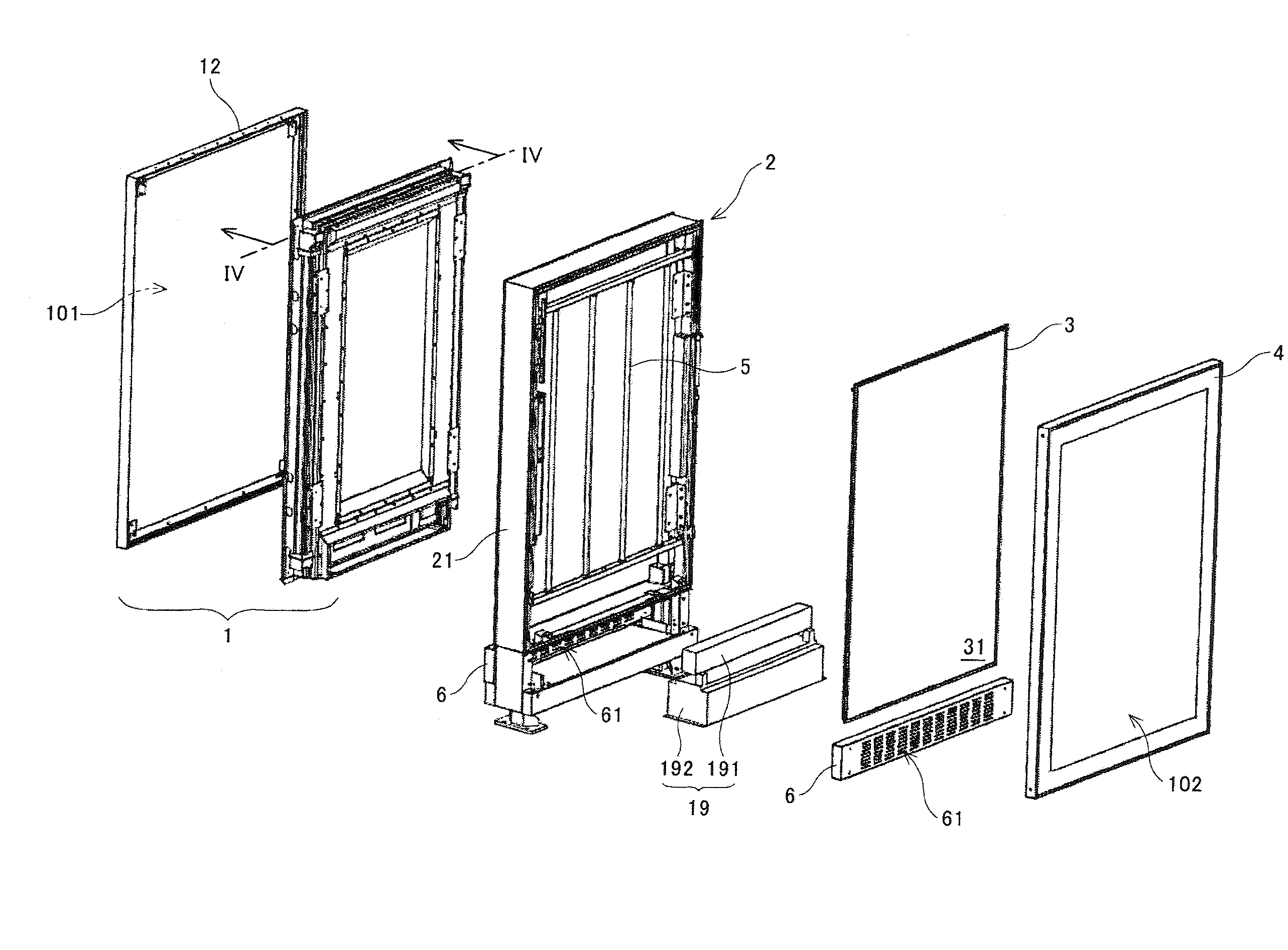
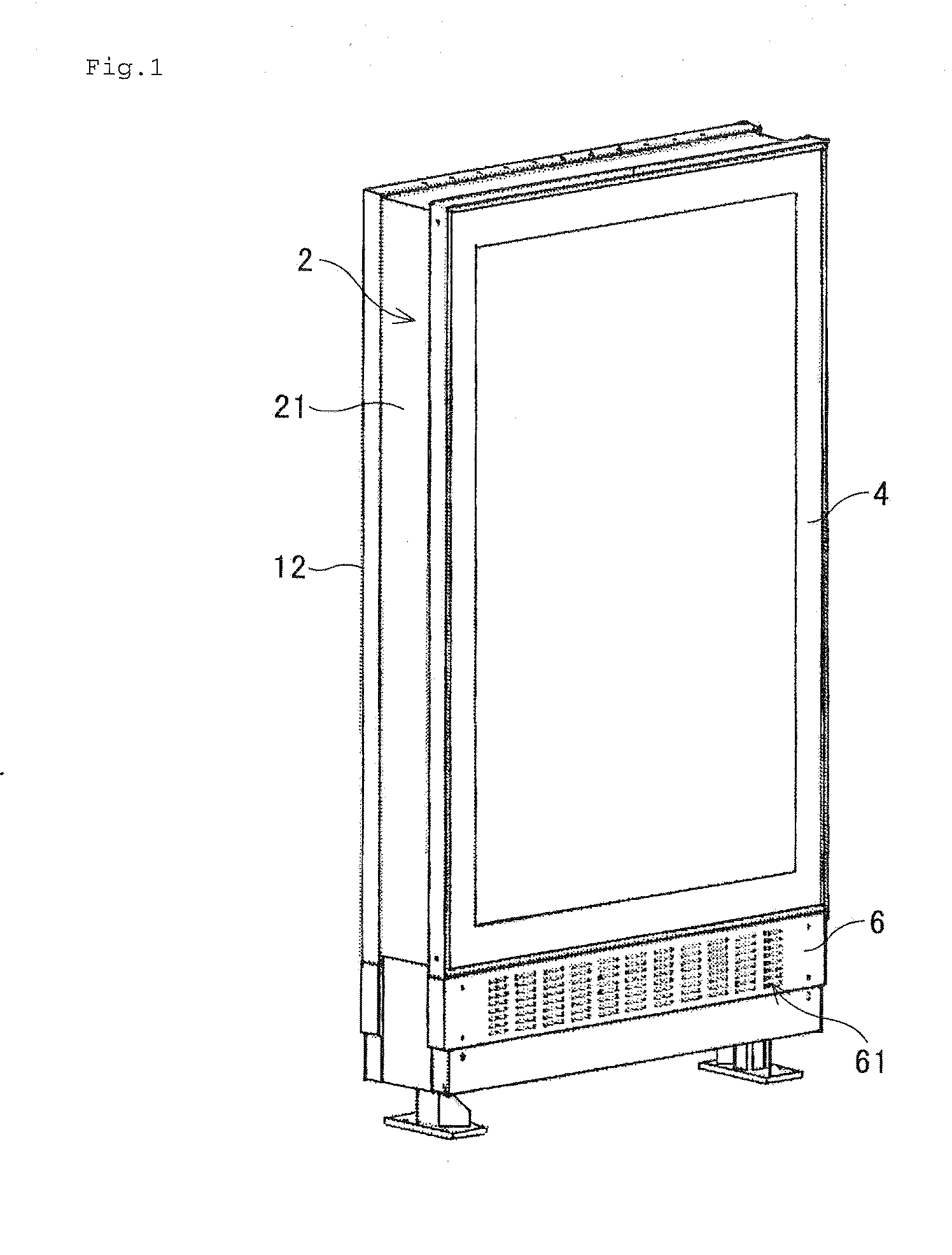
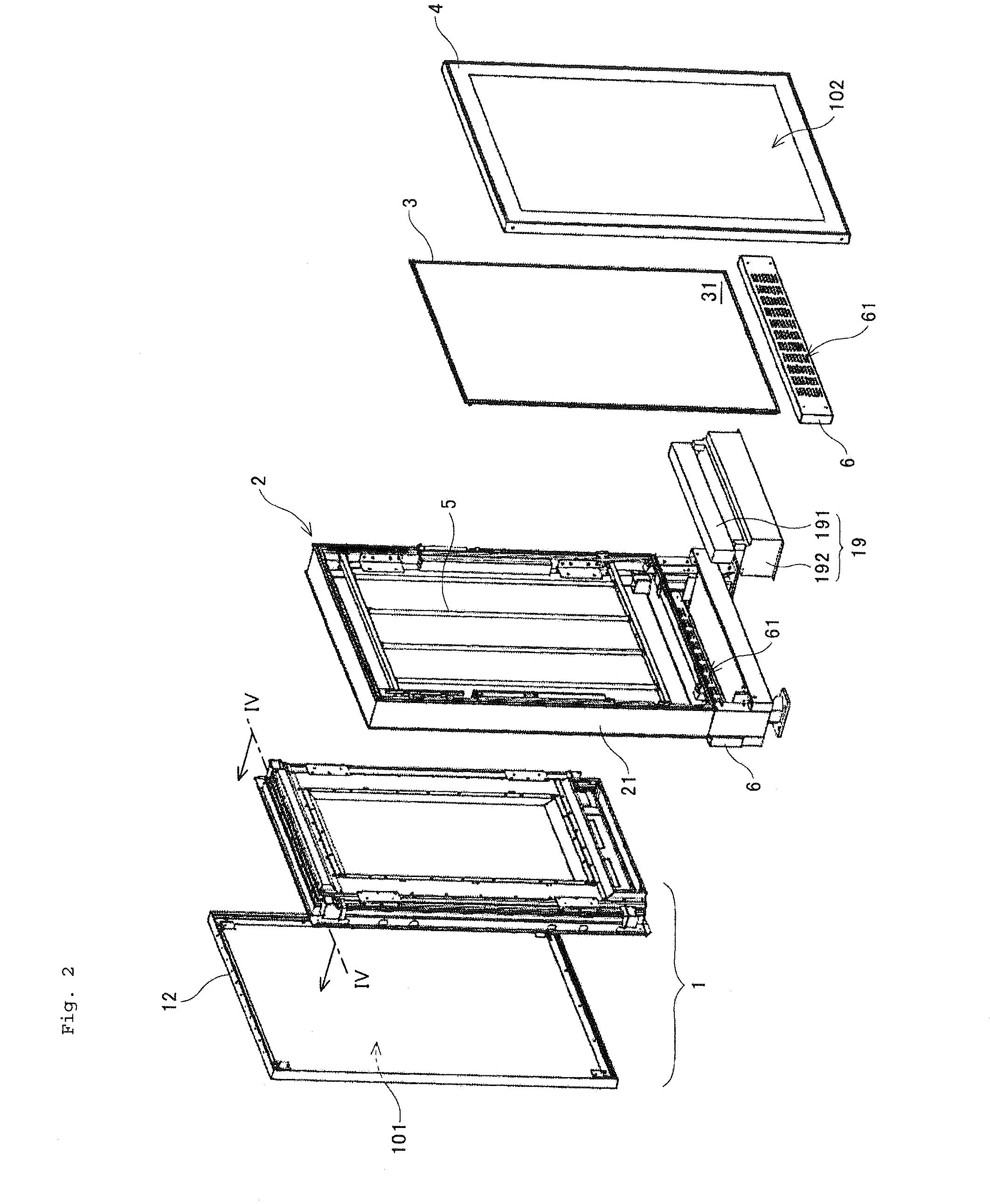
[0040]As shown in FIG. 1 the display system has a flat rectangular appearance, and as shown in FIG. 2, it includes a display apparatus 1, support stand 2, backboard 3, cover 4, fluorescent light fittings 5, and pair of aeration plates 6, 6. The display apparatus 1 displays an image on the surface 101 of the display system, and has a liquid crystal display 10 as shown in FIG. 5. The detail of the display apparatus 1 is explained below in section 2 entitled “A display apparatus”.

[0041]The support stand 2 supports the display apparatus 1 and the backboard 3, and a frame part 21 for attaching the display apparatus 1 and the backboard 3 is formed. The frame part 21 has a structure that can contain the display apparatus 1 and the backboard 3. The structure for attaching the display apparatus 1 to the sup...


PUM


Abstract

A display apparatus has a display panel, an accommodating part accommodating the display panel, a circulation path surrounding the accommodating part, a heat exchanger which collects a heat from the circulation path, an electronic circuit arranged at the back side of the accommodation part, which controls the display panel, wherein, the circulation path exists between the accommodating part and the electronic circuit.

Description

[0001]This application claims priority under 35 U.S.C. §119 to Japanese Pat. App. Nos.: 2008-310196, filed Dec. 4, 2008; 2008-310197, filed Dec. 4, 2008; 2008-310198, filed Dec. 4, 2008; 2008-310199, filed Dec. 4, 2008; and, 2008-310200, filed Dec. 4, 2008. Each of the above-identified applications is incorporated herein by reference in their entirety.BACKGROUND OF THE INVENTION[0002]1. Field of the Invention[0003]The present invention relates to a display system, especially, a display system for installation outdoors.[0004]2. Description of Related Art[0005]Conventionally, plane surface type displays, such as liquid crystal displays (LCDs), are widely used. However, most of the conventional liquid crystal displays are designed for indoor installation, and consequently measures to protect them from environmental conditions such as a rainstorm, dust, snow, etc. are not taken. Therefore, it is difficult to place the liquid crystal display outdoors permanently.[0006]Recently, it has be...

Claims


Application Information

Patent Timeline
Patent Type & Authority Applications(United States)
IPC IPC(8): H05K7/20
CPCG02F1/133308G02F1/133385G02F1/133604G02F2001/133311H05K7/20972G02F2001/133328G02F2201/36G09F9/35G02F2001/133317G02F1/133311G02F1/133317G02F1/133328H05K7/2099
Inventor NAKAMICHI, MASAYATAKAHASHI, SHOUHEITAKE, NOBUYUKI
Owner SANYO ELECTRIC CO LTD
Why Eureka
Try Eureka