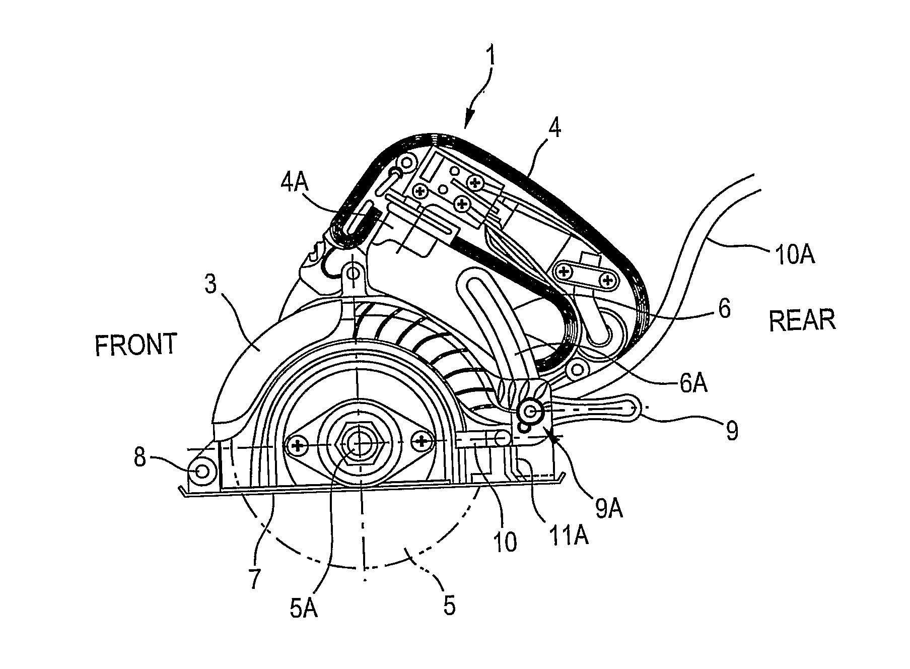
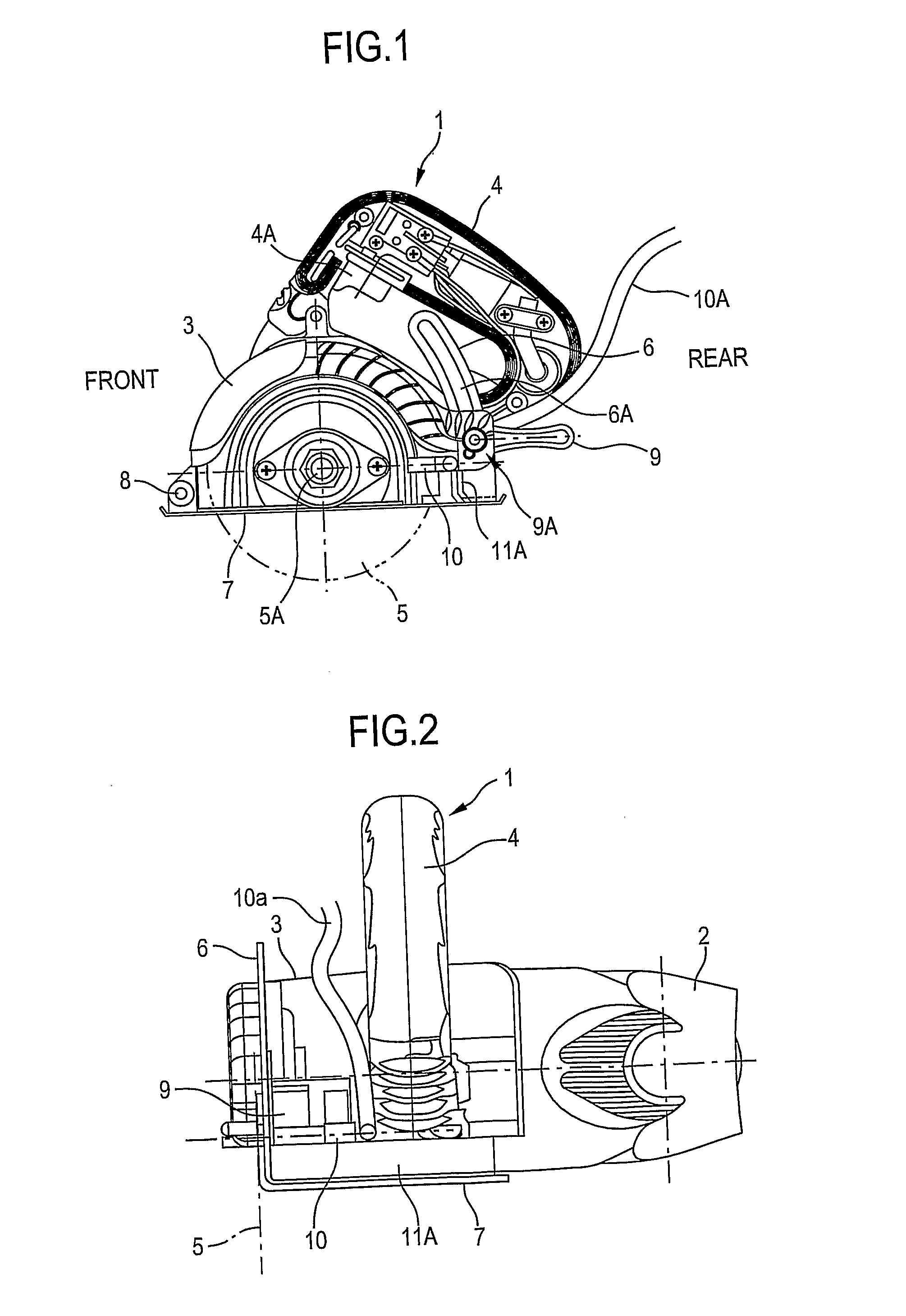
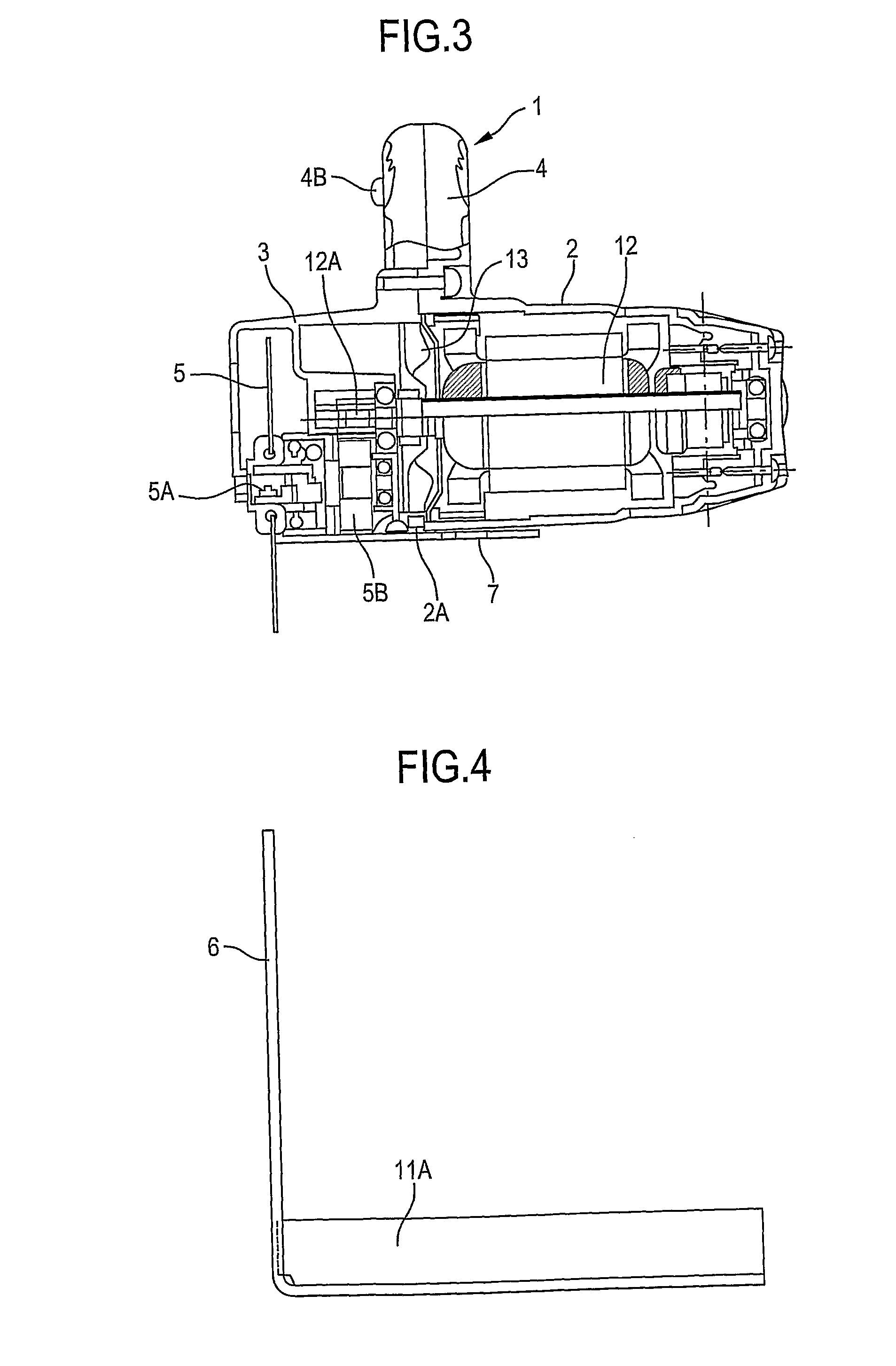
Cutter

a cutting machine and cutting blade technology, applied in the field of cutting machines, can solve problems such as lowering workability, and achieve the effect of avoiding unwanted liquid splashing and improving cutting operation

Active Publication Date: 2010-06-17
HITACHI KOKI CO LTD
View PDF15 Cites 7 Cited by
  • Summary
  • Abstract
  • Description
  • Claims
  • Application Information

AI Technical Summary

Benefits of technology

[0016]Alternatively, the splashboard section is made from an elastic material, and has one end fixed to the top surface of the base, and another end fixed to the housing. With this arrangement, the splashboard section can provide buffering function because of its elasticity or flexibility. Further, such splashboard section can expand or shrink because of this elasticity during pivotal movement of the housing. Th...

Problems solved by technology

This causes low...

Method used


Image

  • Cutter
  • Cutter
  • Cutter

Examples


first embodiment

[0060]With this arrangement, the vertical base end portion 11C2 provides a function the same as that in the splashboard 11A of the Further, the bent portion 11C1 can trap the splashed water directing upward. Thus, excellent splashguard function can be provided. This configuration is particularly advantageous when altering a cutting depth.

[0061]FIG. 9 shows a cutter according to a fourth embodiment of the present invention. A part of the splashboard section 11D is aligned with the circular saw 5 in the cutting direction similar to the foregoing embodiment. However, the splashboard section 11D is positioned at a rearmost end portion of the base 7. Further, the splashboard section 11D is not integral with the link 6 but is connected to the rearmost end portion of the base 7 by welding and extends therefrom in a direction perpendicular to the base 7. An uppermost end of the splashboard section 11D is positioned higher than that of the link 6. Further, a width of the splashboard section...

fifth embodiment

[0063]FIG. 10 shows a cutter according to the present invention. In this embodiment, a splashboard section 11E is made from an elastic material such as a rubber, and protrudes from the base 7 in a direction perpendicular thereto. The splashboard section 11E has one end fixed to the base 7 and another end fixed to the main body 1. The splashboard section 11E is expandable and shrinkable in accordance with a pivotal movement of the main body 1 about the pivot shaft 8 in respect of the protruding direction.

[0064]Any impact due to collision of foreign object against the splashboard 11E can be moderated or dampened since the board 11E is made from elastic material. Further splashguard area can be increased when the splashboard 11E expands as a result of pivotal movement of the main body 1 about the pivot shaft 8. Thus, inadvertent scattering of the splashed water rearward of the base 7 can be restrained.

[0065]In the foregoing embodiments, width of the splash board section 11A to 11E in a...


PUM

PropertyMeasurementUnit
Heightaaaaaaaaaa
Elasticityaaaaaaaaaa

Abstract

A cutter for cutting a workpiece while using a water includes a housing, an electric motor disposed in the housing, a rotation shaft, a base, and a splashboard. The rotation shaft is supported by the housing for rotatably supporting an end tool driven by the electric motor. The base supports the housing, and has a top surface and a bottom surface to be in contact with the workpiece. The end tool has a part protrudable from the bottom surface. The splashboard section is positioned on the top surface and behind the end tool in a cutting direction. The splashboard section protrudes in a direction away from the top surface and extends in a direction substantially parallel to an axial direction of the rotation shaft.

Description

TECHNICAL FIELD[0001]The present invention relates to a cutter, and more particularly, an electrically powered cutter while using liquid such as water for cutting a workpiece.BACKGROUND ART[0002]A conventional cutter such as an electrical stone cutter is shown in FIGS. 11 and 12. The cutter includes a main body 51 provided with a motor 53 and an end tool 52 such as a circular blade driven by the motor 53 for cutting a workpiece such as a concrete.[0003]A housing 54 and a gear cover 55 serve as outer frame of the main body 51. The motor 53 having a motor shaft is installed in the housing 54, and a fan 56 is also installed in the housing 54 coaxially with the motor shaft for cooling the motor 53. A gear portion 57 is installed in the gear cover 55 for deceleratingly transmitting the rotation of the motor shaft to a rotation shaft 58 of the end tool 52.[0004]A base 59 is disposed below the main body 51 and is configured to allow the end tool 52 to protrude from a lower surface of the b...

Claims


Application Information

Patent Timeline
IPC IPC(8): B28D1/04B28D7/02
CPCB28D7/02B28D1/045Y10T83/263
Inventor TADOKORO, NAOKITACHIBANA, TOSHIHIKO
Owner HITACHI KOKI CO LTD
Why Eureka
Try Eureka