Customizing Barcode Images for Particular Displays

a barcode image and display technology, applied in the field of customizing barcode images for particular displays, can solve the problems of not being able to render images, unable to successfully read barcodes, and displaying barcodes on electronic displays

Active Publication Date: 2010-06-17
CODEBROKER
View PDF51 Cites 69 Cited by
  • Summary
  • Abstract
  • Description
  • Claims
  • Application Information

AI Technical Summary

Benefits of technology

[0025]In another aspect of the invention, the barcode includes redundant information and the barcode is displayed without at least some of the redundant information. The technique takes advantage of the fact that the display device produces a perfectly-rendered barcode. In the present context, redundant information is any information contained in the barcode which is not required by the barcode reader to either locate the barcode or to read the barcode's message. Redundant information may include but is not limited to information which repeats all or part of the message, location information which is not needed to locate the barcode, or information which may be used to correct errors made in reading the displayed barcode.

Problems solved by technology

Problems of Displaying Barcodes on Electronic Displays
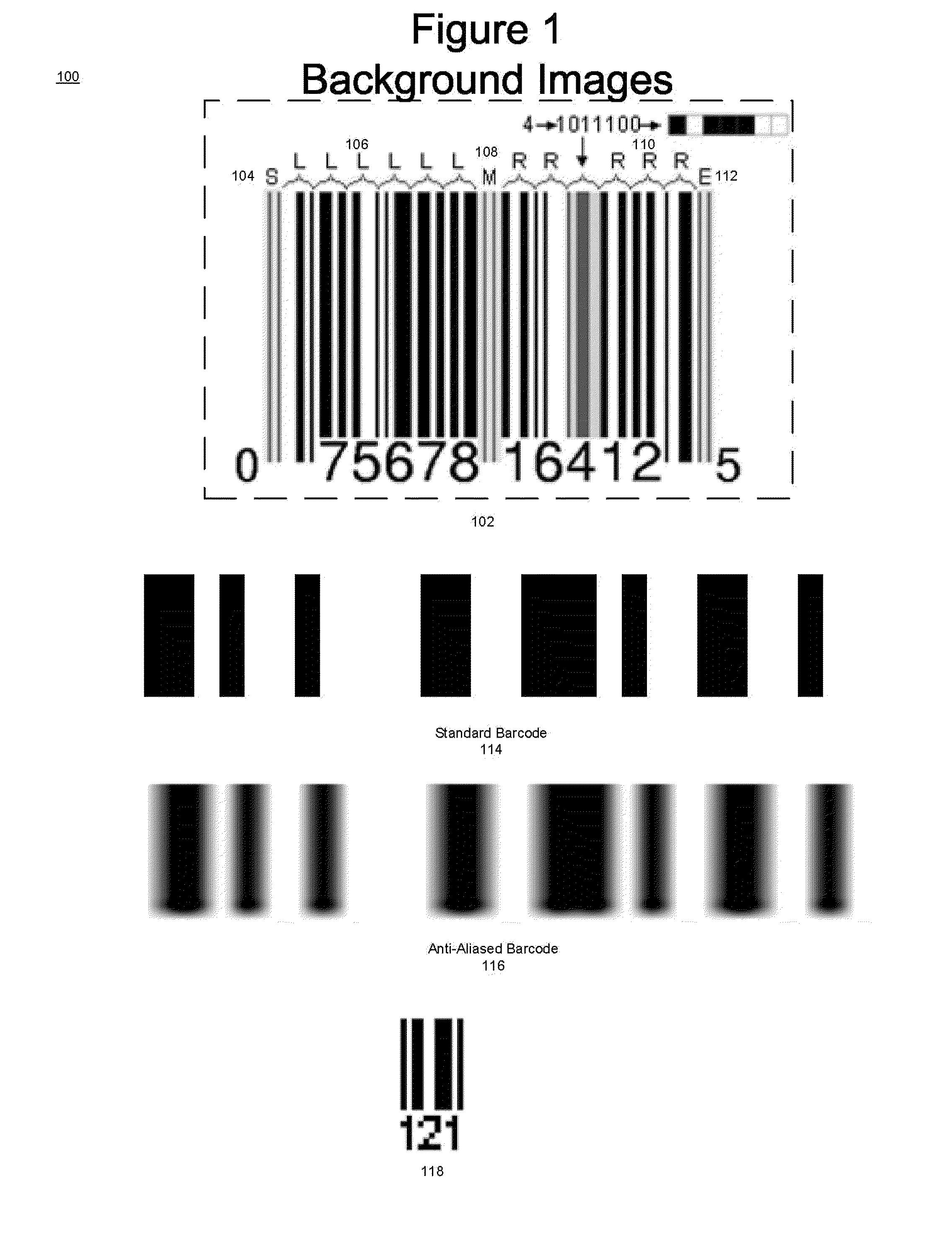
For example, it is not possible to render an image which is 2.5 pixels wide (or high).
The fuzziness resulting from antialiasing makes it difficult or impossible for a barcode reader to successfully read the barcode.
Effect 3) A third problem is that the elements of the barcode must have the minimum width that is required for the barcode reader to read the element.
If a barcode is displayed with elements whose width in pixels is less than the minimum width, many barcode readers will not be able to read the barcode.
On reflective displays such as LCD displays, the minimum width problem is further exacerbated by glass or plastic coatings which sit above the display device and which tend to distort both the light received from the barcode reader and the light produced by the display and thus to distort the image of the barcode.
Further, the amount by which the width in pixels of the barcode may be increased is limited by the requirement that the entire barcode must fit in the display.
However, these solutions do not address the issue of ensuring maximum readability of the displayed barcode.

Method used


Image

  • Customizing Barcode Images for Particular Displays
  • Customizing Barcode Images for Particular Displays
  • Customizing Barcode Images for Particular Displays

Examples


Embodiment Construction

[0035]Overview of the Invention

[0036]The solution to the problem of sizing a barcode that is displayed in a pixel display in order to ensure maximum readability of the barcode by a barcode reader has three parts.

[0037]The first part is to orient / rotate the barcode in the display so that it can be sized for maximum readability. Three different possibilities are shown in FIG. 4:

[0038]1) display the code horizontally as shown in 402

[0039]2) display the code vertically as shown in 404

[0040]3) Rotate / orient the barcode so that it is displayed diagonally on the display as shown in 406, 408, 410, and 412. What is meant by diagonal in the present context is any orientation of the barcode in which the barcode is not parallel to the sides of the display.

[0041]The second part of the solution is to expand the barcode so that it is readable by the barcode reader.

[0042]The third part of the solution involves enabling further expansion of the displayed barcode by one or more of the following metho...


PUM


Abstract

Techniques for ensuring maximum readability of barcodes displayed in pixel displays. The techniques use the characteristics of the pixel display to determine the form of the barcode in the pixel display. Determination of the form includes determining a size of the barcode which renders the barcode's elements easily readable by a barcode reader and a shape, and or orientation of the barcode in the display which permits the entire barcode to be displayed in the display. Additionally, in a barcode with redundant information, the amount of redundant information may be reduced in the displayed barcode. The techniques may be applied to both one-dimensional and two-dimensional barcodes.

Description

CROSS-REFERENCE TO RELATED APPLICATIONS[0001]This application claims is a continuation-in-part to co-pending International Application No. PCT / US07 / 10270, filed on Apr. 27, 2007, which in turn claims priority to U.S. provisional patent application No. 60 / 795,505, entitled “Customizing barcode images for particular displays”, filed on Apr. 27, 2006. The international application and U.S. provisional application are incorporated into the present patent application by reference for all purposes.STATEMENT REGARDING FEDERALLY SPONSORED RESEARCH OR DEVELOPMENT[0002]Not applicable.REFERENCE TO A SEQUENCE LISTING[0003]Not applicable.BACKGROUND OF THE INVENTION[0004]1. Field of the Invention[0005]The present invention relates to systems in which transactions are performed by displaying a barcode on a device that is not part of a point of sale system. In most cases these devices will be portable or mobile in nature such as a cellular telephone. The point of sale system will read the displayed...

Claims


Application Information

Patent Timeline
Patent Type & Authority Applications(United States)
IPC IPC(8): G06T11/20
CPCG06K1/12G06K19/06112G06K19/06028G06K7/1095G02B6/006G06Q20/3274G06T3/60
Inventor SLAVIN, DANSMRZLIC, PERO
Owner CODEBROKER
Why Eureka
Try Eureka