

Surface mounted lighting fixture
- Summary
- Abstract
- Description
- Claims
- Application Information
AI Technical Summary
Benefits of technology
Problems solved by technology
Method used
Image

Examples
Embodiment Construction
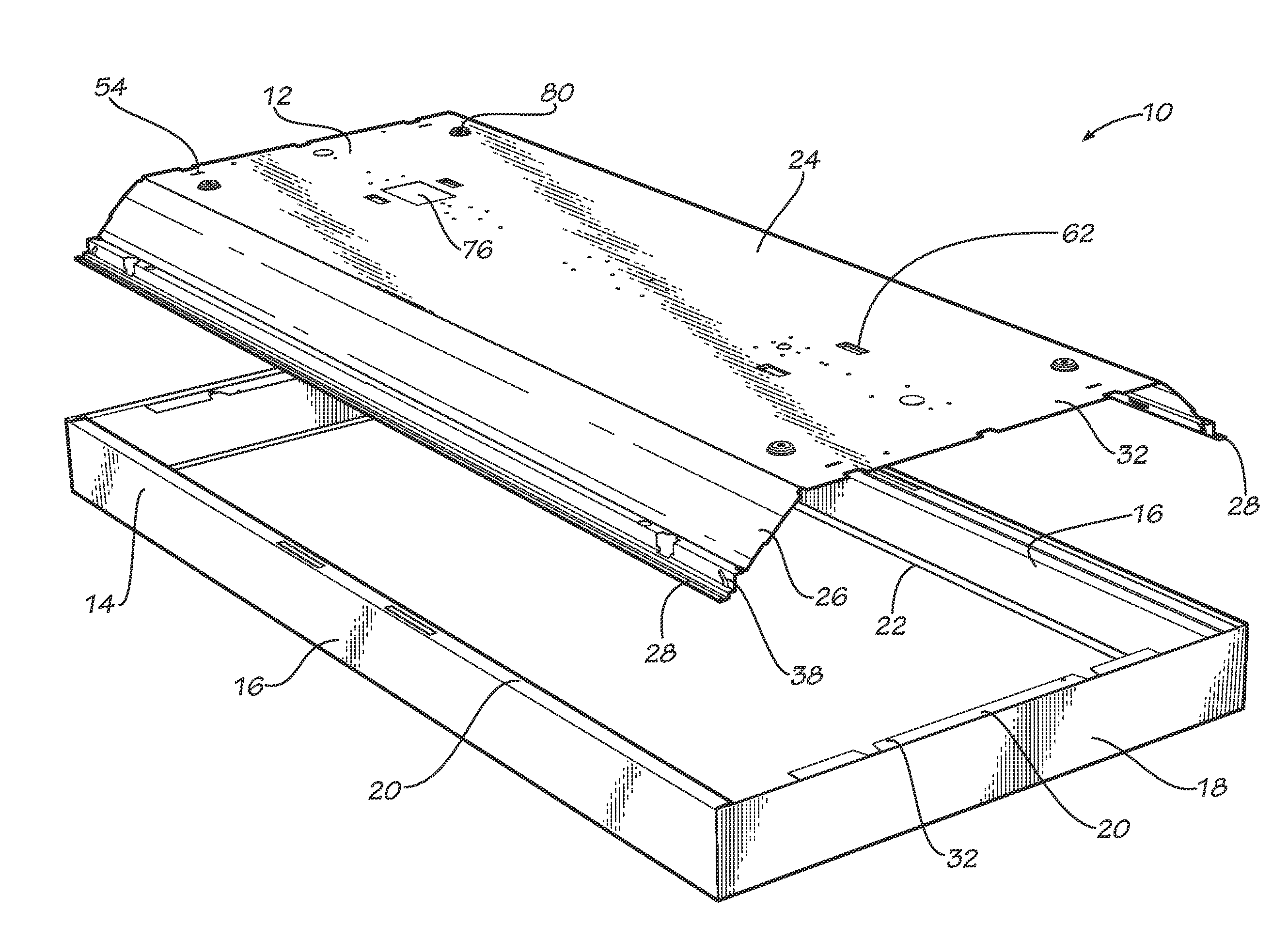
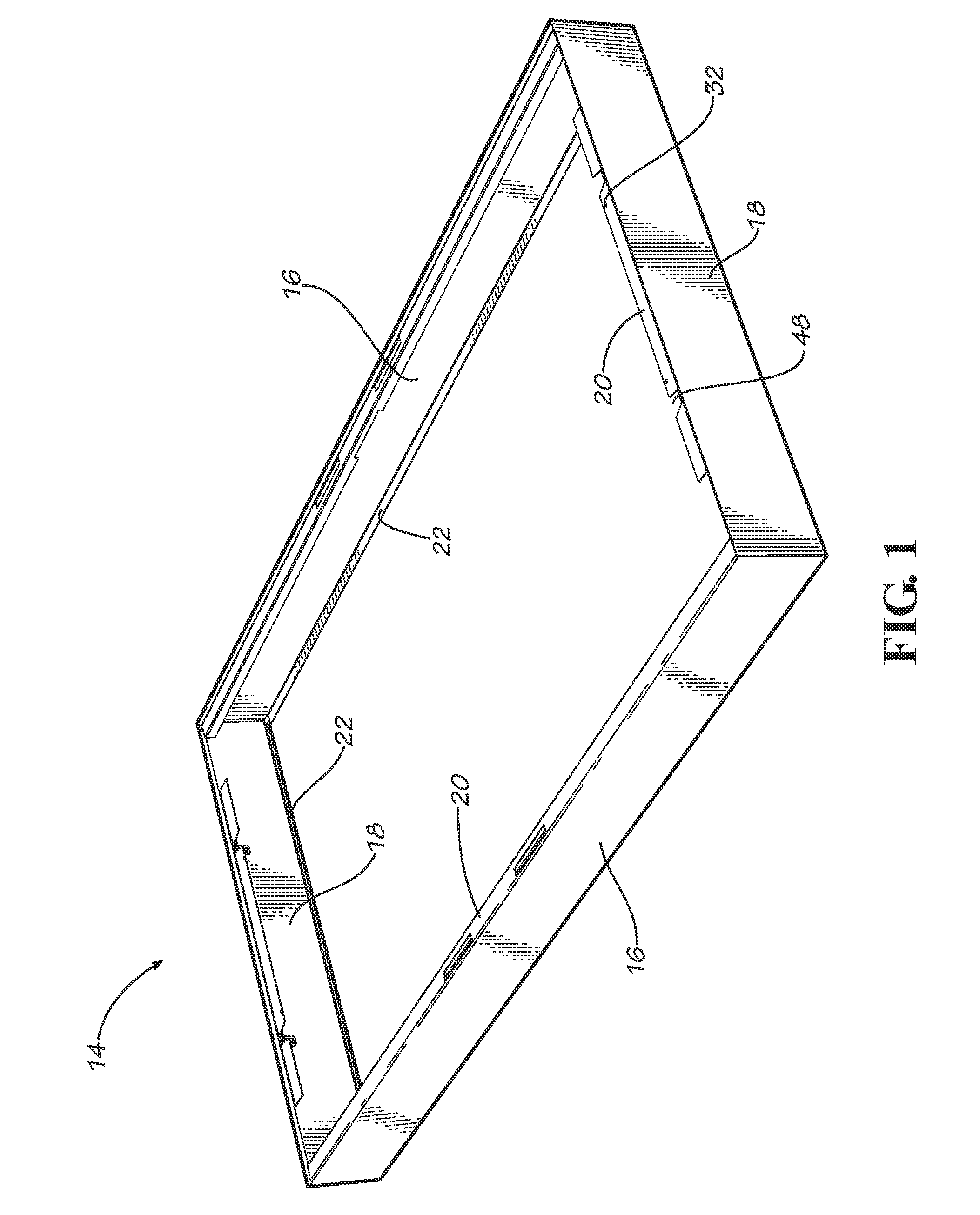
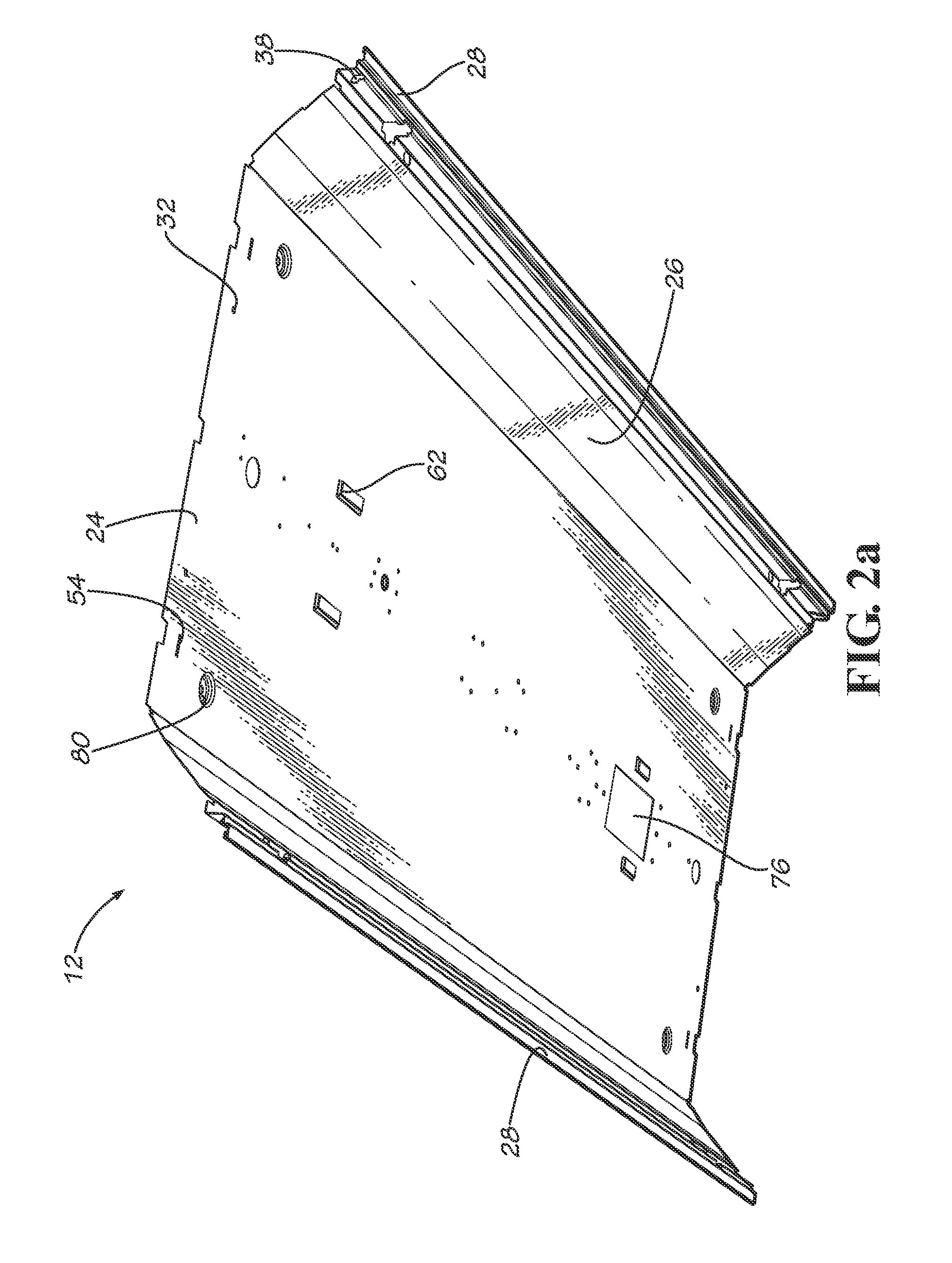
[0006]Embodiments of the invention include surface mounted lighting fixtures having a troffer channel and a frame that extends around the troffer channel. The troffer channel includes a top wall and side walls. To impart a “back” to the fixture, the troffer channel is positioned in the frame so that the upper surface of the lighting fixture is defined by the top wall of the troffer channel and so that the fixture is mounted to a ceiling via the top wall of the troffer channel. The side walls of the troffer channel are preferably angled relative to the top wall to reflect light out of the fixture as desired. Tie brackets, lamp holder brackets, electrical components, and traditional louvers and lensed door components may be supported by the lighting fixture.
[0007]An installation bracket may be provided to facilitate installation of the lighting fixture. Such brackets may be mounted to the ceiling and used to suspend the fixture to allow the installer to perform the necessary wiring an...
PUM
 Abstract
Description
Claims
Application Information