Aid Apparatus

a technology of a splint and a handle, which is applied in the field of splint apparatuses, can solve the problems of muscle strain and back injuries, the movement of the two arms must be adjusted very precisely to each other, and it is not difficult to predict the cost of special care in the near futur

Inactive Publication Date: 2010-06-24
SHL GRP AB
View PDF9 Cites 24 Cited by
  • Summary
  • Abstract
  • Description
  • Claims
  • Application Information

AI Technical Summary

Benefits of technology

[0018]One object of the present invention is to provide a relatively simple aid apparatus of the type stated in the preamble, with which patients can be displaced following an ergonomic movement path from a sitting position to a standing position and vice versa.
[0019]Another object of the present invention is to provide a relatively simple aid apparatus of the type stated in the preamble, which is homely acceptable designed in order to facilitate for patients to move through narrow passageways and obstacles, such as doorways and doorsteps.
[0026]This solution provides the advantage that a patient follows an ergonomic movement path, which is characterized in that the upper body of a patient involves a slightly forward movement and a major upward movement. Moreover, the slightly backward component of motion imparted to the shins of the patient and the above mentioned components of motion imparted to the upper body of the patient by the straps minimize strains on the knees, shins, hip joints and on the pelvis.
[0029]having the handgrip (31) positioned on the slightly inclined column (30) at a distance that encourage the seated patient to hold on to it so that his centre of gravity is shifted forward,
[0035]According to another aspect of the present invention, there is provided an aid apparatus comprising a wheeled base frame means, a support column means, a lifting mechanism means and a control box means, wherein the slightly inclined column (30), a pair of bracket plates (33), a part of the U-shaped lifting arm (40); the pair of bracket sleeves (41), the actuator (45) and / or the control box means (50) are covered by a waterproof cover (60). Further, all metallic components and joints are treated according to well known methods to avoid corrosion. Thus, it will make easier for the patient to even use said aid apparatus in wet rooms.
[0037]According to another aspect of the present invention, there is provided an aid apparatus comprising a wheeled base frame means, a support column means, a lifting mechanism means and a control box means, wherein front castor means and rear castor means, which are adapted to be attached to the wheeled base frame means, comprise wheels designed so that the wheels of the front castor means have a larger diameter than the wheels of the rear castor means. This solution provides the advantage to the aid apparatus to pass over obstacles as doorsteps by a simple manner.

Problems solved by technology

It is not hard to predict that the costs for special care within the near future will raise due to the increasing number of elderly people.
Such attempts are often avoided both from the patients and the care givers due to the fear that the patients can fall and receive lesions.
When such attempts are done, sometimes the patients are so heavy that the care givers may injury themselves and / or may in a lapse of time result in muscle strains and back injuries.
A drawback of this apparatus is that the movements of the two arms must be adjusted very precisely to each other.
The apparatus is therefore relatively complex and in general relatively susceptible to malfunction and expensive to produce.
The slings are place under the arms of a patient and the patient is leaning backward, which causes an unpleasant feeling of insecurity to the patient.
These lifting and / or transferring devices suffer from a number of drawbacks e.g.:
the physical size of these devices is so large that it is almost impossible to maneuver and pass through narrow door passages;
uncomfortable slings that are place under the arms of a patient, making the patient to lean backward, which causes an unpleasant feeling of insecurity to the patient, when he is raised from a sitting position to a standing position;
many complicated adjustable parts of the devices;
none of these devices is intended to be used in wet rooms.
Generally, heretofore, there has not been available a single concept which solves the above-mentioned problems.

Method used


Image

  • Aid Apparatus
  • Aid Apparatus
  • Aid Apparatus

Examples


Embodiment Construction

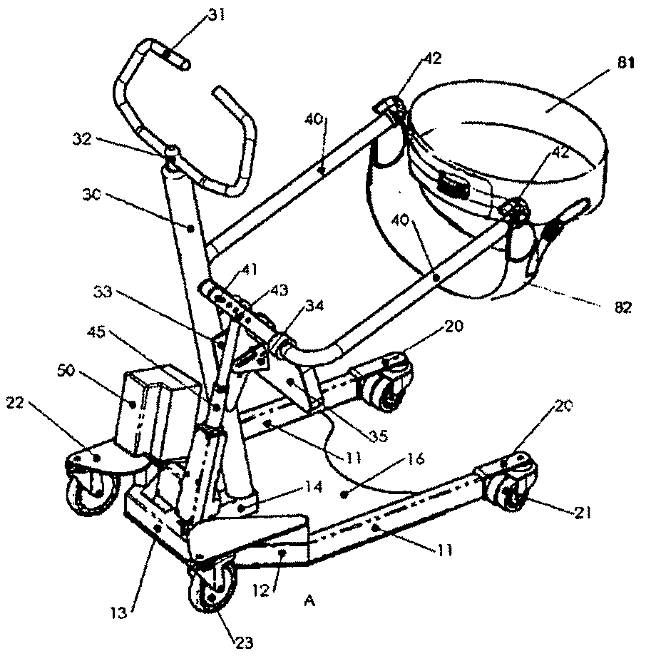
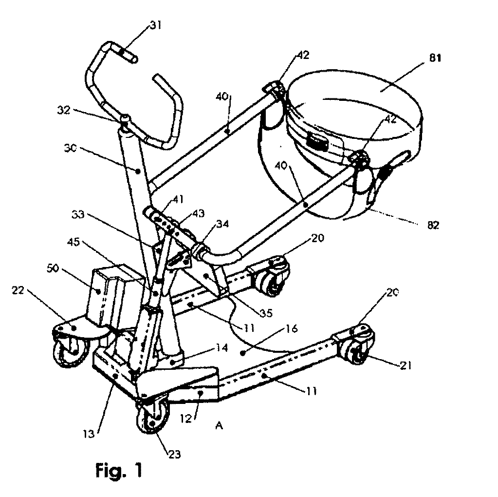
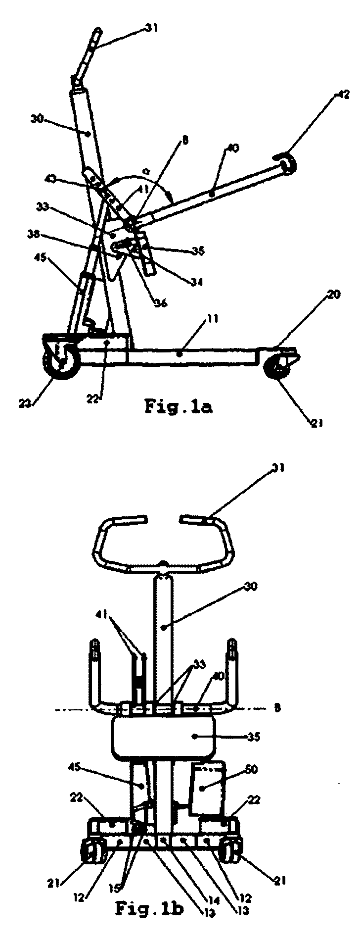
[0053]Referring to the FIGS. 1 to 1c, the aid apparatus illustrated therein comprises a wheeled base frame means, a support column means, a lifting mechanism means and a control box means.

[0054]The wheeled E-shaped base frame means comprises a base frame (10).

[0055]In one embodiment, the base frame (10) comprises two outer legs (11), two beveled legs (12), a front leg (13), a middle leg (14) and a footplate (16), which is arranged between the two outer legs (11). The two outer legs (11), which are parallel to one another and with a predetermined length, extends from the open end of the base frame in a longitudinally direction until they are bended inwards a predetermined angle and having a predetermined length, hereunder the two beveled legs (12). The two beveled legs (12) are bended inwards again in order to form the front leg (13) at the closed end of the base fame (10). Finally, the middle leg (14) extends longitudinally from the middle part of the front leg (13) and wherein said...


PUM


Abstract

The present invention relates generally to an aid apparatus for enabling the assisted mobility of a disable person e.g. to be raised from a sitting position to a standing position, transferring and vice versa. The aid apparatus comprises: a wheeled base frame means; a support column means comprising a handgrip (31); a lifting mechanism means comprising a sling (80), including a waist strap (81) and thigh strap; a U-shaped lifting arm (40) with attaching means (42) carrying said sling (80) and an actuator (45); and / or a control box means (50); wherein the handgrip (31) is positioned on the slightly inclined column (30) at a distance that encourage a seated patient to hold on to it so that his centre of gravity is shifted forward; and the U-shaped lifting arm (40) is designed for being moved by an actuator (45), whereby due to the patient shifted centre of gravity, the movement of the U-shaped lifting arm (40) transfers components of motion with which the patient can be displaced following an ergonomic movement path.

Description

TECHNICAL FIELD[0001]The present invention relates generally to an aid apparatus for enabling the assisted mobility of a disable person e.g. to be raised from a sitting position to a standing position, transferring and vice versa.BACKGROUND ART[0002]Today, there is a large number of patients; e.g. disable, old and physically challenged persons; who are limited to beds, wheelchairs, chair or toilets and who need the assistance of care givers; e.g. therapists, relatives; to help them to a standing position from a sitting position or to help them to be transferred from a bed and / or a wheelchair.[0003]Some of these patients live in special living homes and other in their ordinary homes. The special living homes are becoming twice as costly as home care. It is not hard to predict that the costs for special care within the near future will raise due to the increasing number of elderly people. Therefore, it would be very profitable for the society if the elderly people could be taken care ...

Claims


Application Information

Patent Timeline
Patent Type & Authority Applications(United States)
IPC IPC(8): A61G7/10
CPCA61G7/1017A61G7/1046A61G7/1051A61G7/1069A61G2200/36A61G7/1094A61G7/1096A61G2200/34A61G7/1078
Inventor WERNQVIST, GORANSVENSSON, PETERWEDBJER, SUSANNEWERNQVIST, BJORN
Owner SHL GRP AB
Why Eureka
Try Eureka