

Aircraft toilet facility
a technology for toilets and aircraft, applied in the direction of toilet fittings, fuselages, aircraft accessories, etc., can solve the problems of aircraft operator potentially less profitable, aircraft less profitable, and large cabin space occupied by toilets
- Summary
- Abstract
- Description
- Claims
- Application Information
AI Technical Summary
Benefits of technology
Problems solved by technology
Method used
Image

Examples
first embodiment
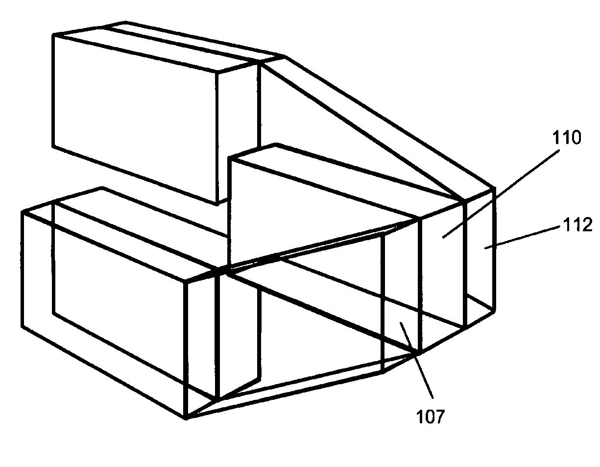
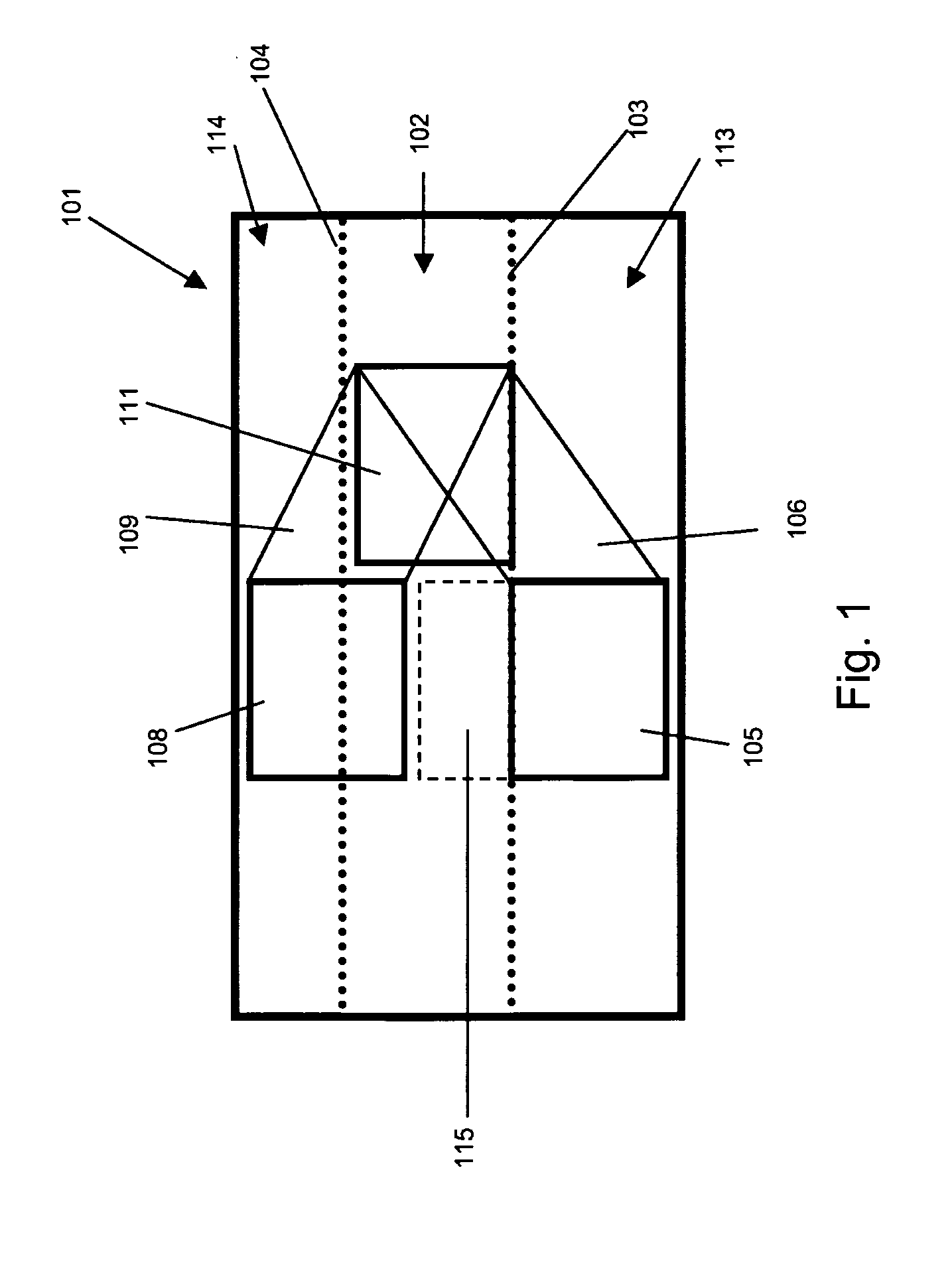
[0027]This first embodiment also shows a third toilet unit 111, fully located between the floor 103 and ceiling 104. The third toilet unit 111 is aligned in the same vertical plane as the first toilet unit 105 and second toilet unit 108. The third door 112 provides access to the third toilet unit 111 and the all three doors 107, 110, and 112, are located next to each other. Therefore, a passenger, when wanting to use the toilet facility, is presented with three doors next to each other.
[0028]As can be seen in FIG. 1, the arrangement of the first toilet unit and second toilet unit may be such that storage space 115 is provided between the units. There may be a gap of 0 mm to the height sufficient to include a further toilet unit between the top of the first toilet unit 105 and the bottom of the second toilet 108. Preferably, the storage space is accessible while the aircraft is flying. It may be accessible to the aircraft crew and / or the aircraft passengers. For example, the storage ...
second embodiment
[0031]FIG. 6 shows a plan view of the invention, as shown in FIGS. 4 and 5, where the first stair set 401 provides access (as indicated by arrows) to the side of the first toilet unit, and the second stair set 402 provides access to the side of the second toilet unit.
[0032]FIG. 7 shows plan view of an alternative to the second embodiment of the invention, where the first stair set 401 and the second stair set 402 include bends 401′ and 402′. The stair sets now provide access to the front of the toilet units (as indicated by an arrow). Advantageously, the first and second toilet unit may be front entry toilet units. This alternative to the second embodiment is equally applicable to the first embodiment as described above, where the ramps include a bend.
[0033]FIGS. 8, 9, and 10, show a third embodiment of the invention. The embodiment features a first toilet unit 805, a second toilet unit 807 and a third toilet unit 809, arranged with the same configuration as described for the first ...
fourth embodiment
[0036]FIG. 11 shows the invention, comprising a first toilet unit 1101, a second toilet unit 1102, a third toilet unit 1103, a fourth toilet unit 1104 and a fifth toilet unit 1105. The arrangement is similar to that shown in FIGS. 4 and 5 as described above, with the addition of a the third toilet unit 1103 located beneath the floor of the passenger deck and the fifth toilet unit 1105 located in vertical alignment with the third toilet unit 1103 and partially within the above-ceiling space. In an alternative embodiment, access to the toilet units provided at least partially located in the space above or below the passenger deck may be provided by a ramp, as described in relation to FIGS. 1 to 3.
[0037]It will of course be appreciated that features described in relation to one embodiment of the present invention may be incorporated into other embodiments of the present invention.
[0038]Whilst the present invention has been described and illustrated with reference to particular embodime...
PUM
 Abstract
Description
Claims
Application Information