Vehicle environment monitoring apparatus
a technology of vehicle environment and monitoring apparatus, which is applied in the direction of image enhancement, scene recognition, instruments, etc., can solve the problems of large error in calculated distance, difficult to determine stably the possibility of contact between the object and the vehicle,
- Summary
- Abstract
- Description
- Claims
- Application Information
AI Technical Summary
Benefits of technology
Problems solved by technology
Method used
Image

Examples
first embodiment
[0090]First, the first embodiment of “the monitored object detecting process” will be explained according to the flow chart shown in FIG. 10. In STEP 100, the monitored object detecting unit 26 selects any of the image area extracted by the object extracting unit 20 as the detecting object.
[0091]In subsequent STEP 101, the monitored object detecting unit 26 determines, for the selected image area, whether or not the distance Z1 between the object and the vehicle 10 calculated by the first distance calculating unit 24 is equal to or less than a Zth (corresponds to the predetermined distance of the present invention).
[0092]In FIG. 11(b), a transition of the error of the distance Z1 between the object and the vehicle 10 calculated by the first distance calculating unit 24 using one disparity data to the true distance is indicated by “a”, and a transition of the error of the distance Z2 between the object and the vehicle 10 calculated by the second distance calculating unit 25 using the...
second embodiment
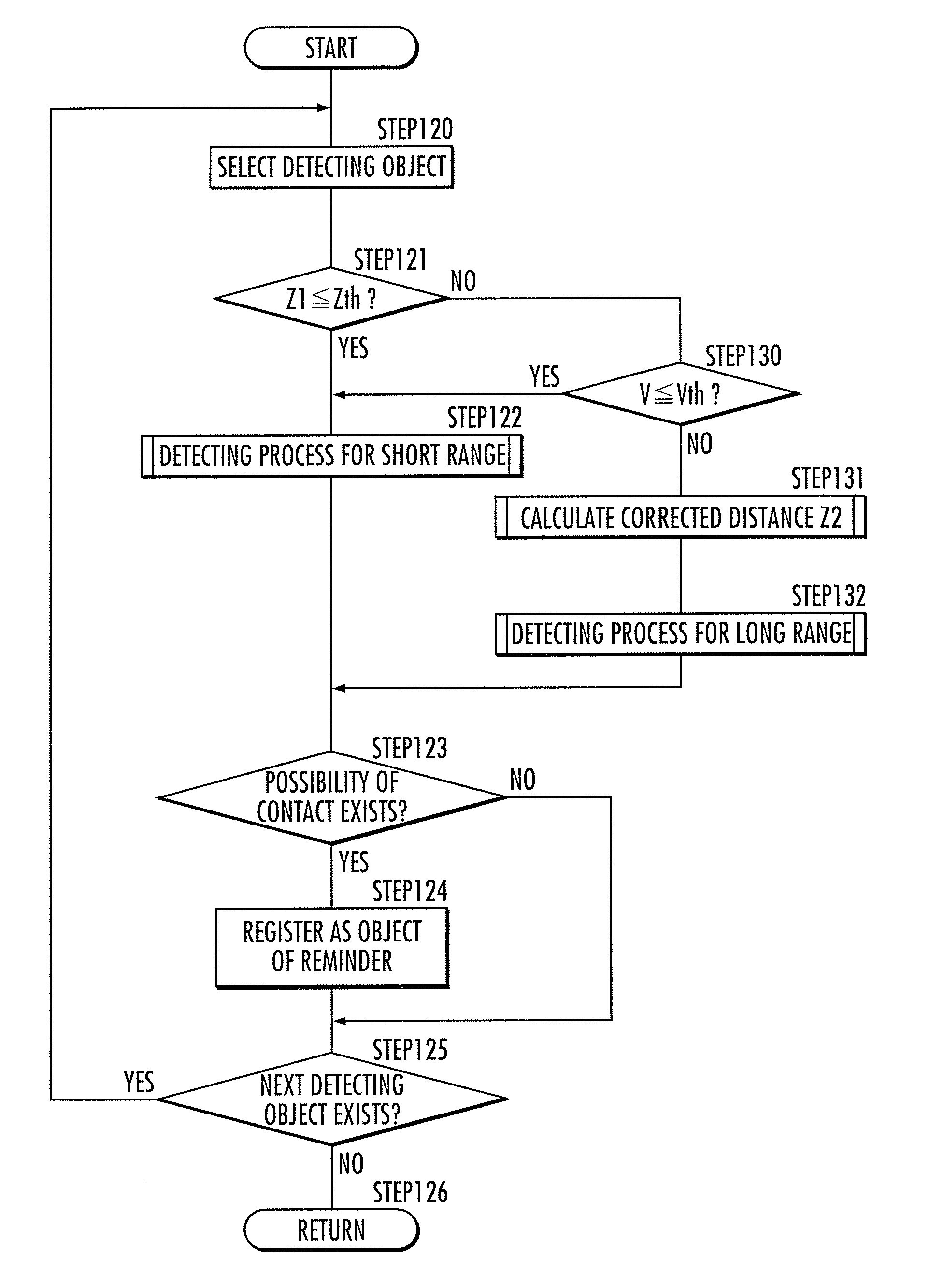
[0108]Next, an explanation will be given on the second embodiment of the “monitored object detecting process”, according to the flow chart shown in FIG. 13. The flow chart in FIG. 13 is the flow chart shown in FIG. 10 added with a determining unit in STEP 130, and the process in STEP 120 through STEP 126 corresponds to the process of STEP 100 through STEP 106 in FIG. 10, and the process in STEP 131 through STEP 132 corresponds to the process of STEP 110 through STEP 111 in FIG. 10. Therefore, the explanations thereof will be omitted.
[0109]In the flow chart of FIG. 13, when the distance Z1 between the object and the vehicle 10 calculated by the first distance calculating unit 24 in STEP 121 is longer than Zth, the process branches to STEP 130, and the monitored object detecting unit 26 determines whether or not the traveling velocity V of the vehicle 10 detected by the vehicle speed sensor 4 is equal to or less than a determination threshold value of the vehicle speed Vth (correspond...
third embodiment
[0114]Next, an explanation will be given on the third embodiment of the “monitored object detecting process”, according to the flow chart shown in FIG. 15. In STEP 140, the monitored object detecting unit 26 selects any of the image area extracted by the object extracting unit 20 as the detecting object.
[0115]In subsequent STEP 141, the monitored object detecting unit 26 determines whether or not the distance Z1 between the object and the vehicle 10 calculated by the first distance calculating unit 24 is within a preset range (Zmin through Zmax) taking Zth as the center, for the selected image area.
[0116]When the distance Z1 calculated by the first distance calculating unit 24 is within the range Zmin through Zmax, then the process proceeds to STEP 142, and the monitored object detecting unit 26 executes the “detecting process for short range”. When it is determined that there is a possibility of contact between the object and the vehicle 10, then the process proceeds from subsequen...
PUM
 Abstract
Description
Claims
Application Information
 - R&D
- Intellectual Property
- Life Sciences
- Materials
- Tech Scout
- Unparalleled Data Quality
- Higher Quality Content
- 60% Fewer Hallucinations
Browse by: Latest US Patents, China's latest patents, Technical Efficacy Thesaurus, Application Domain, Technology Topic, Popular Technical Reports.
© 2025 PatSnap. All rights reserved.Legal|Privacy policy|Modern Slavery Act Transparency Statement|Sitemap|About US| Contact US: help@patsnap.com