

Servo controller
a servo controller and controller technology, applied in the direction of electric controllers, electric programme control, program control, etc., can solve the problems of distorted mechanical system including the movable member b>1/b>, and mechanical system subject to stress, so as to suppress excessive torque of the motor
- Summary
- Abstract
- Description
- Claims
- Application Information
AI Technical Summary
Benefits of technology
Problems solved by technology
Method used
Image

Examples
embodiment 1
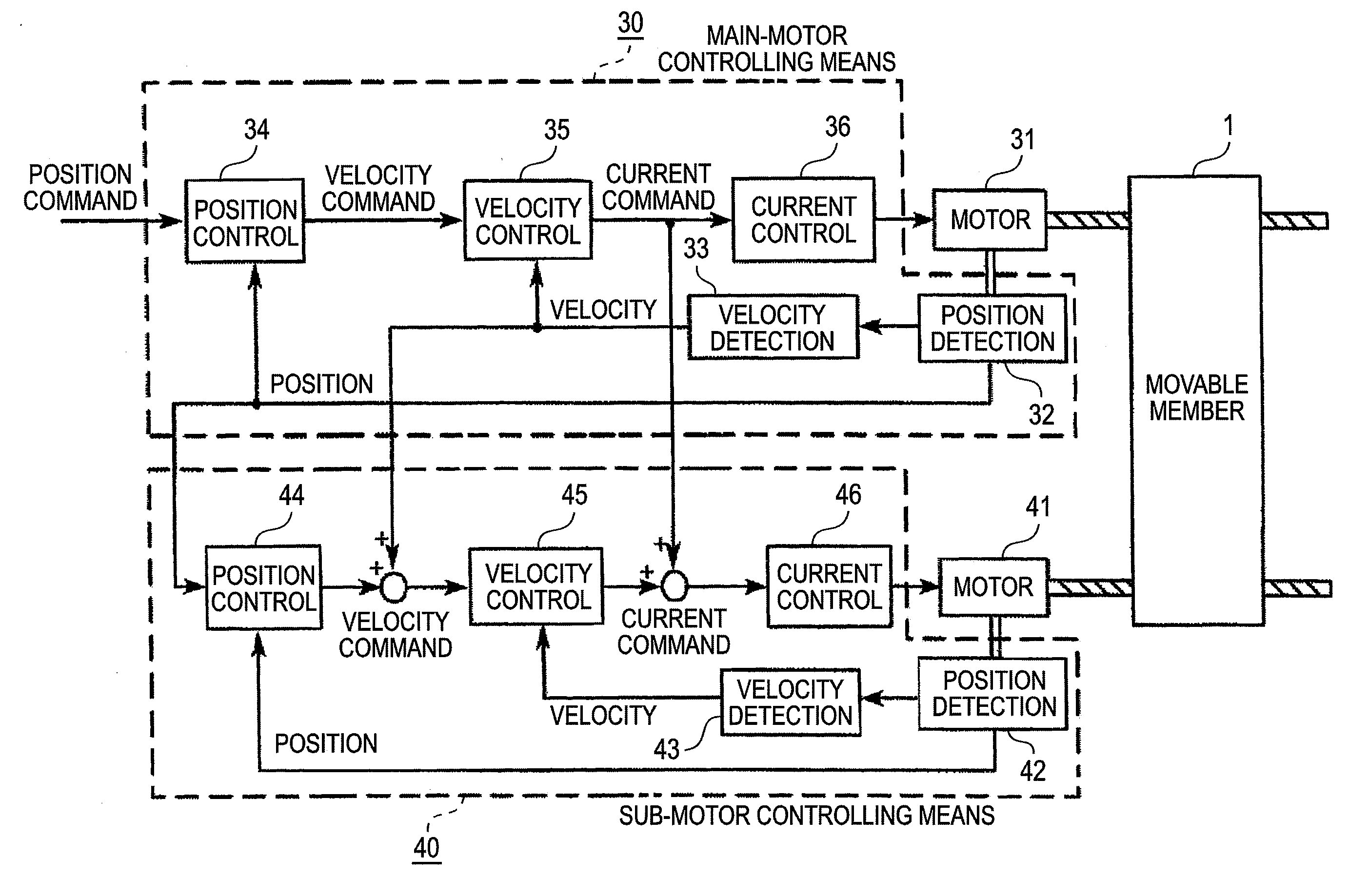
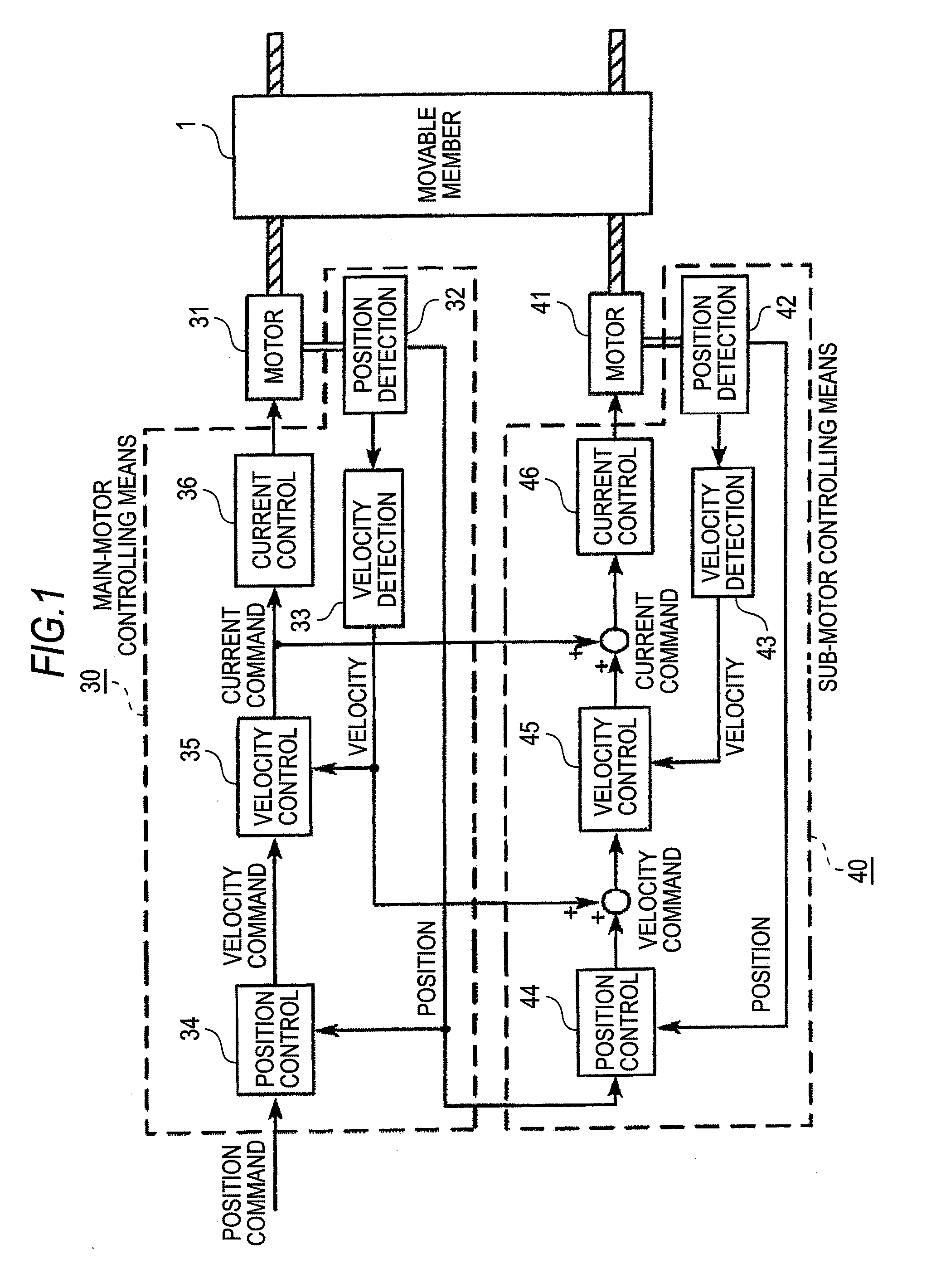
[0051]FIG. 1 shows a block diagram of a servo controller of Embodiment 1 of the invention. In FIG. 1, 31 denotes a main motor, 41 denotes a sub motor, 1 denotes a movable member which is driven by the main motor 31 and the sub motor 41, 30 denotes main-motor controlling means which controls driving of the main motor 31, and 40 denotes sub-motor controlling means which controls driving of the sub motor 41.
[0052]The main-motor controlling means 30 is configured by main-motor position detecting means 32, main-motor velocity detecting means 33, position controlling means 34, velocity controlling means 35, and main-motor current controlling means 36. The position controlling means 34 and the velocity controlling means 35 constitute main-motor position controlling means. The position controlling means 34 receives a position command given from a higher level controller which is not shown, and outputs a velocity command so that the position of the main motor 31 detected by the main-motor po...
embodiment 2
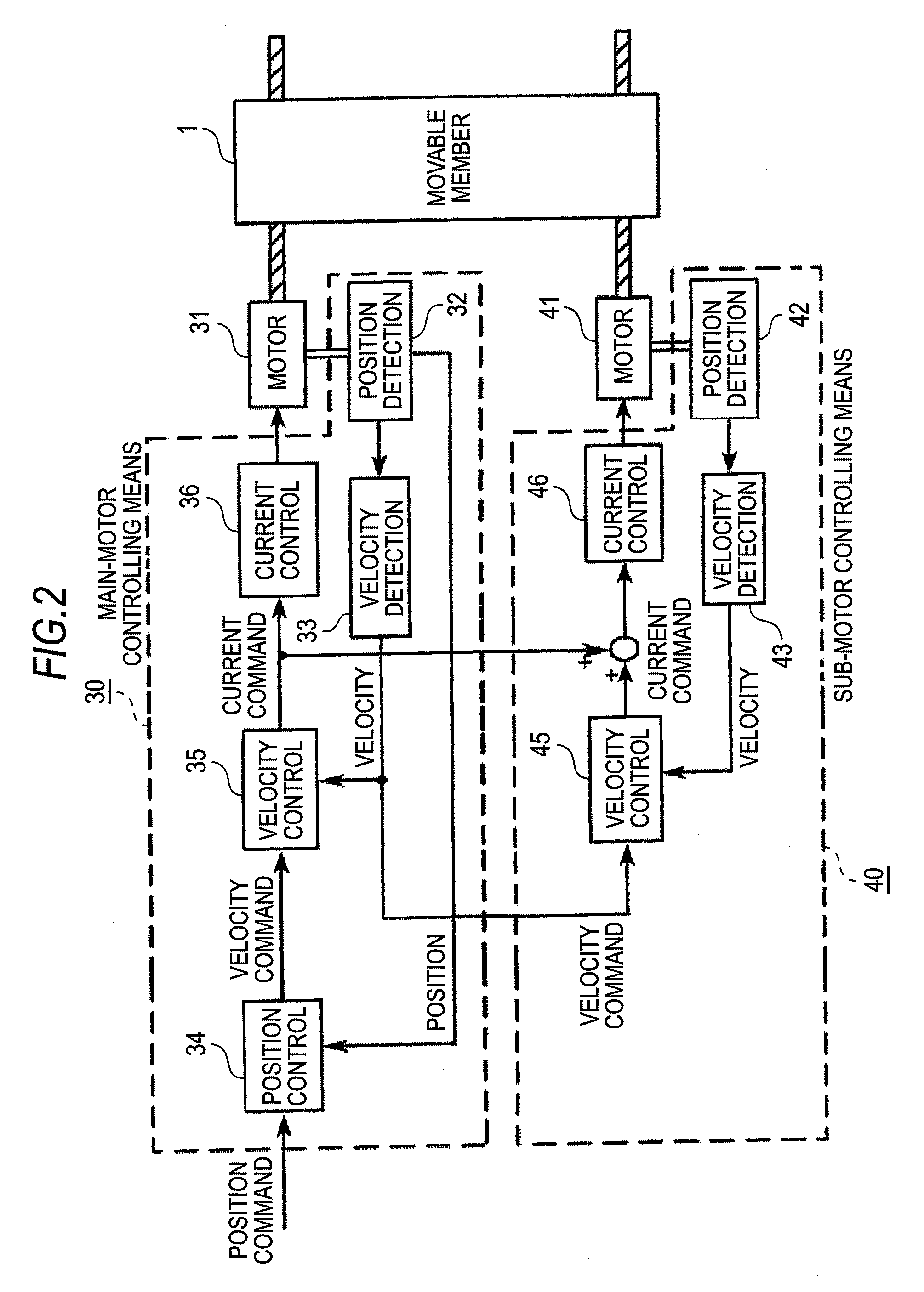
[0059]FIG. 2 shows a block diagram of a servo controller of Embodiment 2 of the invention. The same components as FIG. 1 are denoted by the identical reference numerals, and their description is omitted. FIG. 2 is configured by omitting the position control loop of the sub-motor controlling means 40 from FIG. 1 showing Embodiment 1. According to this configuration, the velocity of the main motor 31 detected by the main-motor velocity detecting means 33 is input to the sub-motor velocity controlling means 45 as the velocity command.
[0060]In the conventional servo controller, the current command is increased until the position deviation is eliminated, thereby causing the motors to generate an excessive torque. In the servo controller of Embodiment 2, by contrast, since the sub-motor controlling means 40 is not provided with a position control loop, the phenomenon that the current command is increased until the position deviation is eliminated does not occur, and the generation of an e...
PUM
 Abstract
Description
Claims
Application Information