
Removable portable computer device

Active Publication Date: 2010-07-08
LENOVO (BEIJING) CO LTD
View PDF20 Cites 69 Cited by
  • Summary
  • Abstract
  • Description
  • Claims
  • Application Information

AI Technical Summary

Benefits of technology

[0007]An object of the present invention is to provide a removable portable computer device with better portability.
[0033]In the present invention, the flat panel computer is removably mounted on the back plate through the second connection structure, when the computer is required to be used at other location and a mass of keyboard input is not needed, it only requires to take off the flat panel computer from the back plate so as to easily carry the flat panel computer from one location to another location for use, thus the portability is greatly increased.

Problems solved by technology

However, since the flat panel computer uses a touch pad to realize the input instead of a keyboard, it is hard to completely replace the notebook computer.
But, no matter which structure is employed, the display screen is fixed on the mainframe, and both the display screen and the mainframe are not removable from each other.

Method used


Image

  • Removable portable computer device
  • Removable portable computer device
  • Removable portable computer device

Examples


first embodiment

The First Embodiment

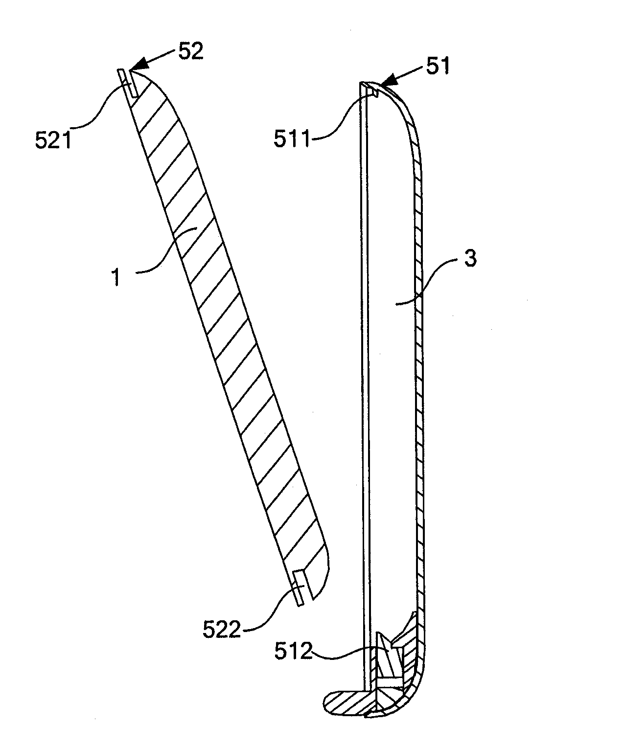
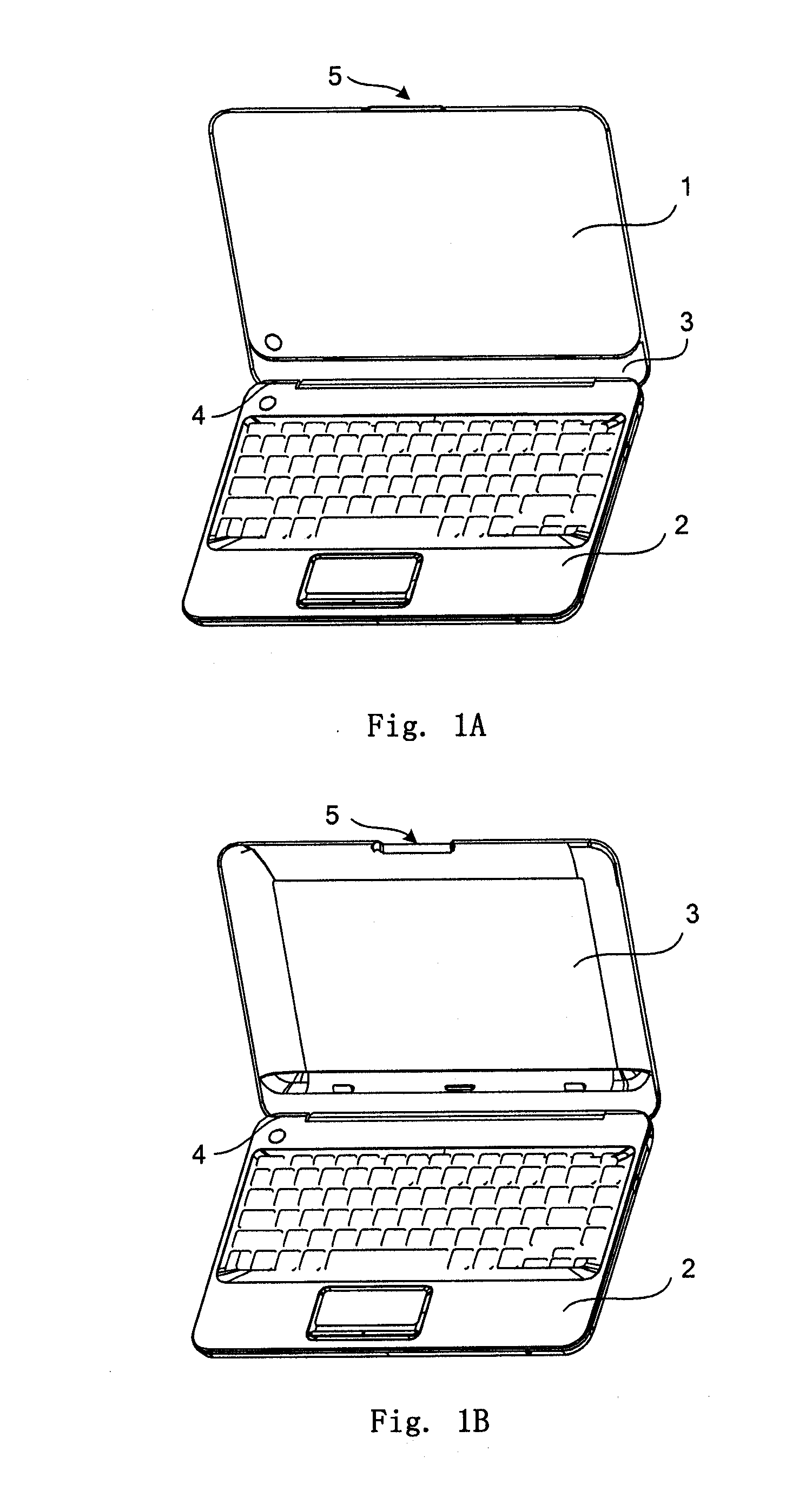
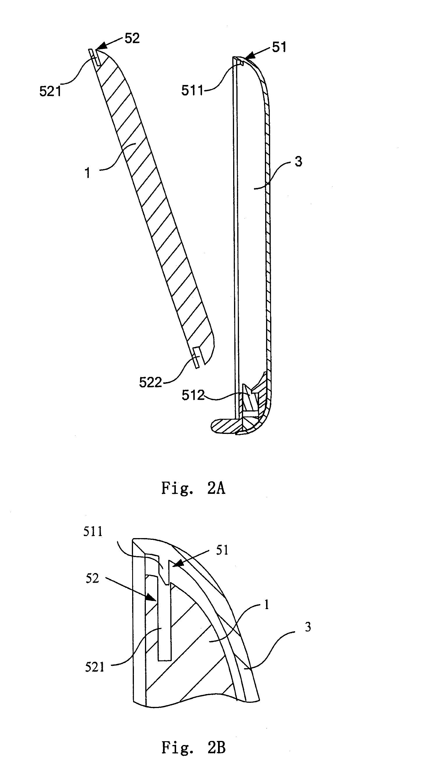
[0060]As shown in FIGS. 1A and 1B, a removable portable computer device according to a first embodiment of the present invention comprises: a flat panel computer 1 having abilities or functions of displaying and calculating, a base 2, a back plate 3, a first connection structure 4 and a second connection structure 5; the first connection structure 4 is provided on the base 2 for connecting with the back plate 3. By means of the first connection structure 4, the back plate 3 is rotatably provided on the base 2. The first connection structure 4 can employ the existing rotation shaft shown in FIG. 5, which allows the back plate 3 to rotatably fixed on the base 2. Alternatively, the first connection structure can take the form of any removable means which is provided on the base 2 in a removable manner. The second connection structure 5 is provided on both the back plate 3 and the flat panel computer 1 for connecting the back plate 3 with the flat panel computer 1; t...

second embodiment

The Second Embodiment

[0066]The structures of the embodiment is substantially the same as those of the first embodiment, differences therebetween reside mainly as shown in FIG. 3, the first engagement portion 51 comprises an upper hook 511 and a lower clamp groove 514 with like construction as that of the first embodiment. The upper hook 511 is also provided on the upper portion of the back plate 3; the lower clamp groove 514 is adapted to engage with the bottom portion of the flat panel computer 1 and provided at the lower portion of the back plate 3, that is, when the bottom portion of the flat panel computer 1 is inserted into the lower clamp groove 514, the lower clamp groove 514 is able to well accommodate the bottom portion of the flat panel computer 1. The second engagement portion 52 comprises an upper slot 521 adapted to engage with the upper hook 511 and provided at the bottom portion of the flat panel computer 1, the configuration of the upper hook 511 is similar as that i...

third embodiment

The Third Embodiment

[0070]As shown in FIGS. 4A, 4B, 4C, the back plate 3 according to the third embodiment of the present invention is further provided with a first pattern printing zone 31 thereon, the flat panel computer 1 is further provided with a second pattern printing zone 11 thereon, and a pattern with specific effect is formed by a first pattern printed on the first pattern printing zone 31 and a second pattern printed on the second pattern printing zone 11. As shown in the figures, the first pattern printed in the first pattern printing zone 31 includes floral leafs and flowers without sprays, and the second pattern printed in the second pattern printing zone 11 includes sprays without floral leafs and flowers, both patterns are superposed to form a pattern with an unitary effect. Furthermore, other patterns having three-dimensional effects can also be printed as desired.


PUM


Abstract

The present invention provides a removable portable computer device. In an embodiment, the portable computer device includes: a flat panel computer; a base; a back plate; a first connection structure through which the base is connected with the back plate; a second connection structure through which the back plate is connected with the flat panel computer. The flat panel computer is removably connected onto the back plate through the second connection structure. In the present invention, the flat panel computer is removably mounted on the back plate through the second connection structure. When the computer is required to be used at other location and a mass of keyboard input is not needed, it only requires to take off the flat panel computer from the back plate so as to easily carry the computer from one location to another location for use, thus the portability is greatly increased.

Description

TECHNICAL FIELD[0001]The present invention relates to a portable computer device, more particularly, to a notebook computer.BACKGROUND OF THE INVENTION[0002]Along with the popularization and application of the notebook computer in various fields, people increase the requirement of the portability of notebook computer. Presently, the way to deal with this situation is to continuously attempt to reduce the whole weight and thickness of the entire notebook computer so as to have better portability.[0003]However, no matter which way to employ, the display screen of notebook computer is fixed on the main frame through certain connection structures. When in use, particularly in changing the using location, the entire computer is required to move to the place to be used.[0004]Occurrence of the flat panel computer overcomes the defects of the portable computer in portability at a certain extent. However, since the flat panel computer uses a touch pad to realize the input instead of a keyboa...

Claims


Application Information

Patent Timeline
IPC IPC(8): G06F1/16H05K7/00
CPCG06F1/1626G06F1/1632
Inventor TIAN, PINGXIA, XIAOSONGCHEN, XINGXIN, ZHIFENG
Owner LENOVO (BEIJING) CO LTD
Learn More