
Method and apparatus for cryptographic key storage wherein key servers are authenticated by possession and secure distribution of stored keys

a cryptographic key and key server technology, applied in the field of cryptographic systems, can solve the problems of affecting the security of encrypted data, and unable to guess the key through exhaustive trial and error

Inactive Publication Date: 2010-07-08
CA TECH INC
View PDF27 Cites 57 Cited by
  • Summary
  • Abstract
  • Description
  • Claims
  • Application Information

AI Technical Summary

Benefits of technology

The present invention is a key management system that securely stores and manages data on a first system using a control key stored on a key server. The secured data is encrypted using the control key and can only be accessed by an authorized user with knowledge of the access private key. The system generates a request to the key server for a decryption control key and includes a one-time public key. The key server verifies the signature and sends the decryption control key to the first system, which then decrypts the data using the one-time private key. This ensures that the data remains secured in transport. The technical effect of this invention is to provide a secure and efficient way to manage data on a first system.

Problems solved by technology

Preferably, the key used to secure data is selected from a sufficiently large set of possible keys that an attacker cannot guess the key by exhaustive trial and error, even with the use of large amounts of computing resources.
Unfortunately, if the PIN or password is short enough for the user to remember, it is also short enough for an attacker to guess by exhaustive trial and error, thereby undermining the security of the stored key, and in turn undermining the security of the encrypted data.

Method used


Image

  • Method and apparatus for cryptographic key storage wherein key servers are authenticated by possession and secure distribution of stored keys
  • Method and apparatus for cryptographic key storage wherein key servers are authenticated by possession and secure distribution of stored keys
  • Method and apparatus for cryptographic key storage wherein key servers are authenticated by possession and secure distribution of stored keys

Examples


Embodiment Construction

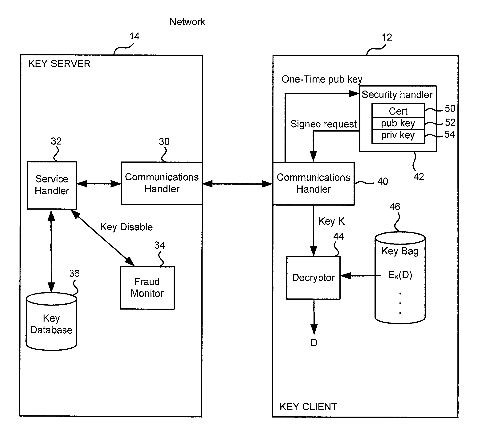
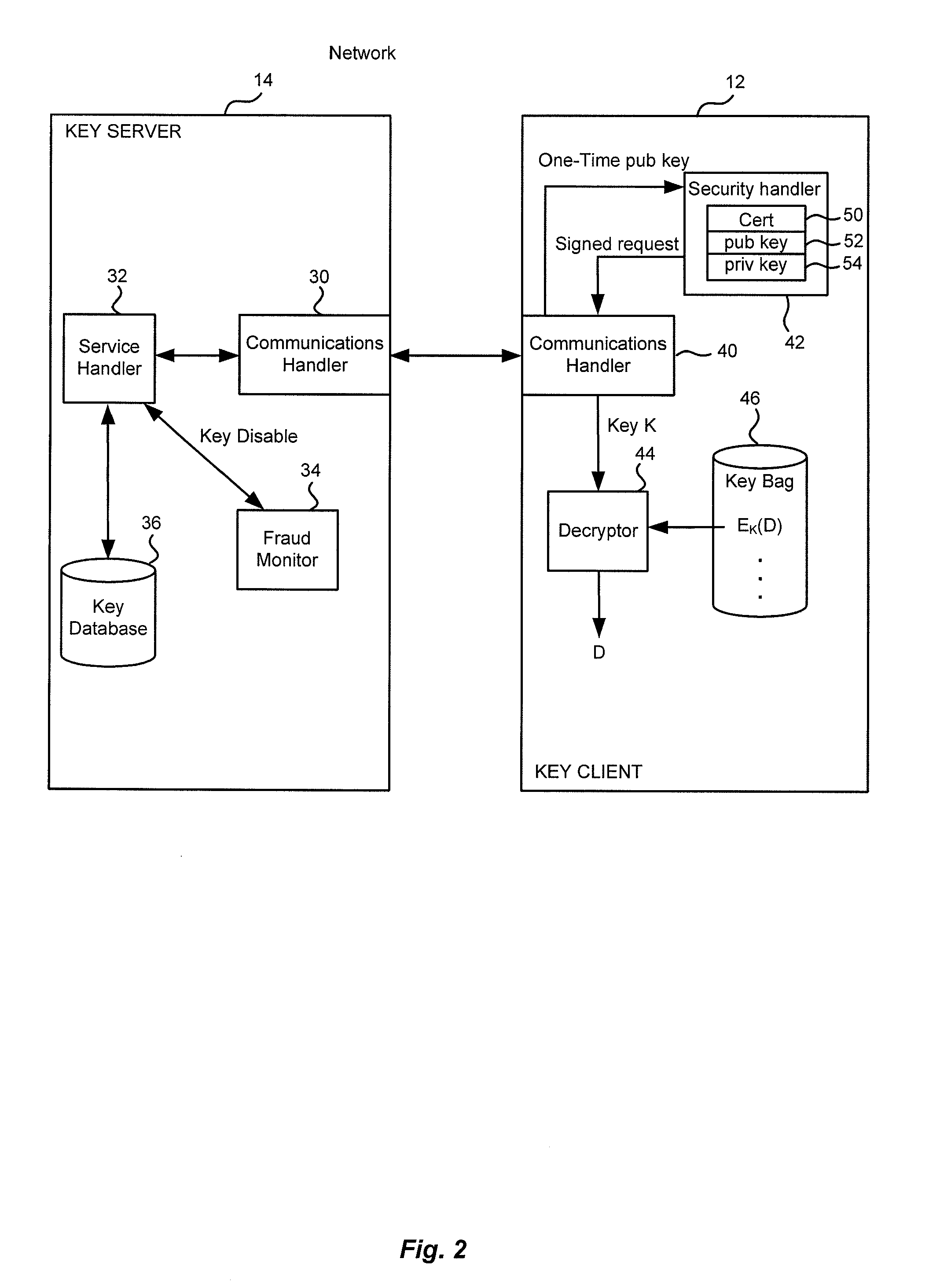
[0015]The systems shown in the figures will first be described with reference to a specific use, that of securing application keys in a “key bag” on a first computer system, such that the application keys in the key bag cannot be accessed without making a request to a remote key server. As used herein, “remote” refers to being separated by a security boundary such that access to a local system does not automatically confer access to the remote system. It should be understood that remote does not require physical separation, but physical separation is one way to provide for remoteness. Given that definition, it should be apparent that a system can be configured such that a local system might be accessible to an attacker while the remote system is not.

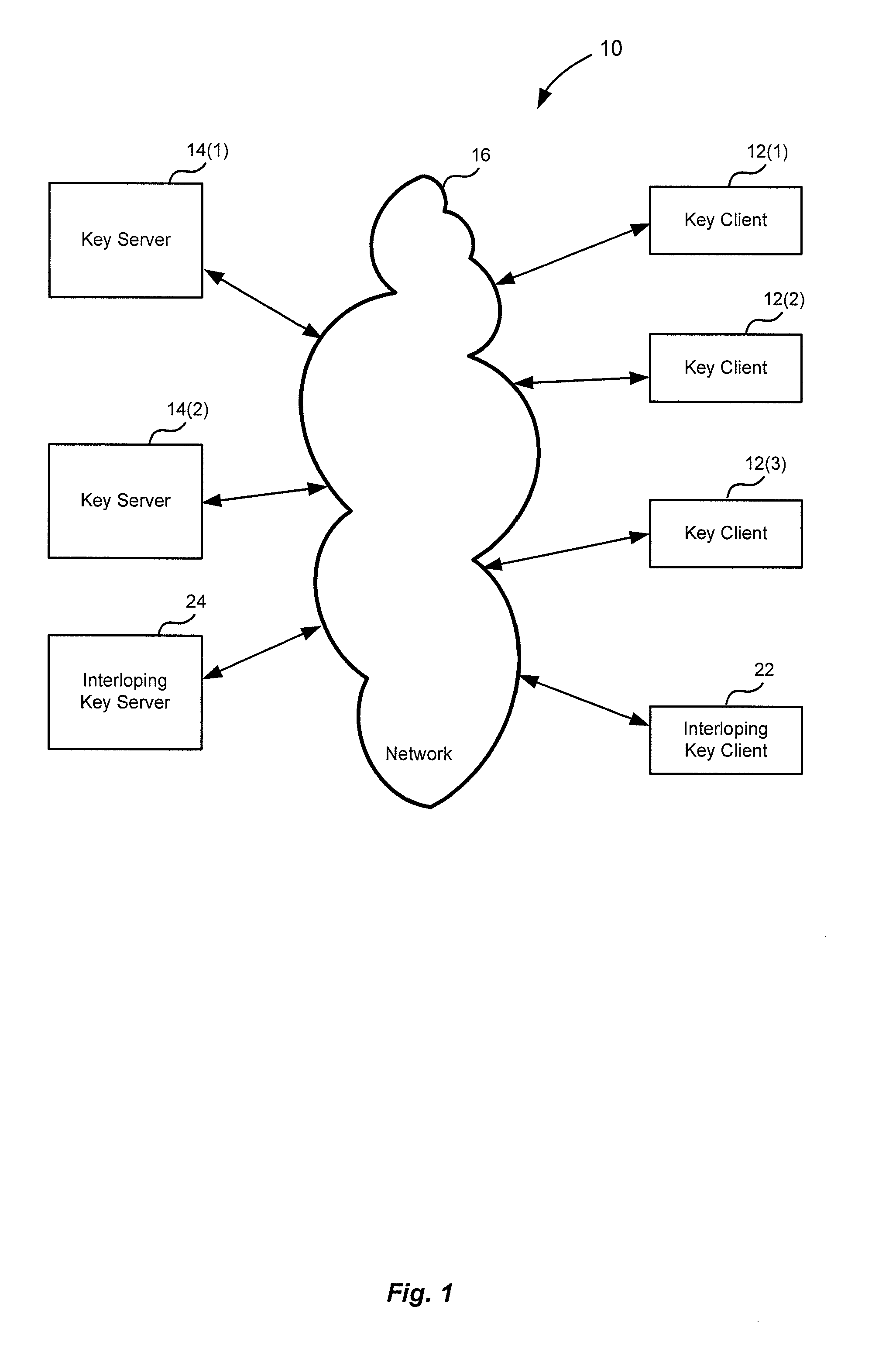
[0016]FIG. 1 is a block diagram of an example arrangement 10 wherein the present invention might be used. As shown there, several key clients 12 and key servers 14 are coupled via a network 16. In specific implementations, key servers 14...


PUM


Abstract

A key management system includes secured data stored on a first system secured by a control key stored securely on a key server. The secured data is secured against attacks such as unauthorized use, modification or access, where authorization to access the secured data is determined by knowledge of an access private key of an access key pair. When an authorized user is to access the secured data, the first system generates a request to the key server, signed with the access private key, wherein the request is for a decryption control key and the request includes a one-time public key of a key pair generated by the first system for the request. The first system can decrypt the decryption control key from the response, using a one-time private key. The first system can then decrypt the secured data with the decryption control key remaining secured in transport.

Description

CROSS-REFERENCES TO RELATED APPLICATIONS[0001]The present application claims priority from and is a non-provisional application of U.S. Provisional Application No. 60 / 274,457, entitled “METHOD AND APPARATUS FOR CRYPTOGRAPHIC KEY STORAGE USING A VERIFIER AND ACCOMMODATING KEY USERS THAT OPERATE INDEPENDENTLY OF THE VERIFIER” filed Mar. 9, 2001, the entire contents of which are herein incorporated by reference for all purposes.FIELD OF THE INVENTION[0002]The present invention relates generally to cryptographic systems and more particularly to key storage apart from data secured by the keys.BACKGROUND OF THE INVENTION[0003]Cryptography is used to secure data. In many systems, knowledge of a key allows access to the data and lack of knowledge of the key secures the data against access. Preferably, the key used to secure data is selected from a sufficiently large set of possible keys that an attacker cannot guess the key by exhaustive trial and error, even with the use of large amounts o...

Claims


Application Information

Patent Timeline
Patent Type & Authority Applications(United States)
IPC IPC(8): H04L9/08H04L9/32H04L9/30
CPCH04L9/0825H04L9/3228H04L9/0897H04L9/083
Inventor ALLEN, ROBERTJERDONEK, ROBERT A.WANG, JOHNWU, TOM
Owner CA TECH INC
Learn More