Electric shaver

Active Publication Date: 2010-07-15
PANASONIC CORP
View PDF16 Cites 15 Cited by
  • Summary
  • Abstract
  • Description
  • Claims
  • Application Information

AI Technical Summary

Benefits of technology

[0019]According to this configuration, the connecting axes for connection of the two link arms to the head part are located asymmetrically with respect to the straight line passing on the center of gravity of the head part

Problems solved by technology

Thus, there is a possibility that the electric shav

Method used


Image

  • Electric shaver
  • Electric shaver
  • Electric shaver

Examples


first modification

(First Modification)

[0058]As shown in FIG. 9, in a first modification of the above embodiment as well, the two pairs of the first link arms 9b are disposed asymmetrically with respect to the straight line Lc. In the first modification, however, the connecting axes C11 and C12 for connection of the two pairs of the first link arms 9b to the interposer 8 are located asymmetrically with respect to the straight line Lc, when viewed in the Y direction. For example, as shown in FIG. 9, the positions of the connecting axes C11 and C12 in the Z direction may be slightly shifted. Such a configuration can make the swing torque based on an input to the connecting axis C11 (swing torque in a counterclockwise direction in FIG. 9) differ from the swing torque based on an input to the connecting axis C12 (swing torque in a clockwise direction in FIG. 9). Consequently, the swing torque can be produced differently depending on the swing direction.

[0059]In addition, in the first modification, the two...

second modification

(Second Modification)

[0060]As shown in FIG. 10, in a second modification of the above embodiment as well, the two pairs of the first link arms 9b are disposed asymmetrically with respect to the straight line Lc. In the second modification, however, the connecting axes C13 and C14 for connection of the two pairs of the first link arms 9b to the head part 3 are located asymmetrically with respect to the straight line Lc, when viewed in the Y direction. For example, as shown in FIG. 10, the positions of the connecting axes C13 and C14 in the Z direction may be shifted. Such a configuration can make the swing torque based on an input to the connecting axis C13 (swing torque in a counterclockwise direction in FIG. 10) differ from the swing torque based on an input to the connecting axis C14 (swing torque in a clockwise direction in FIG. 10). Consequently, the swing torque can be produced differently depending on the swing direction.

[0061]In addition, in the second modification, lengths L...


PUM


Abstract

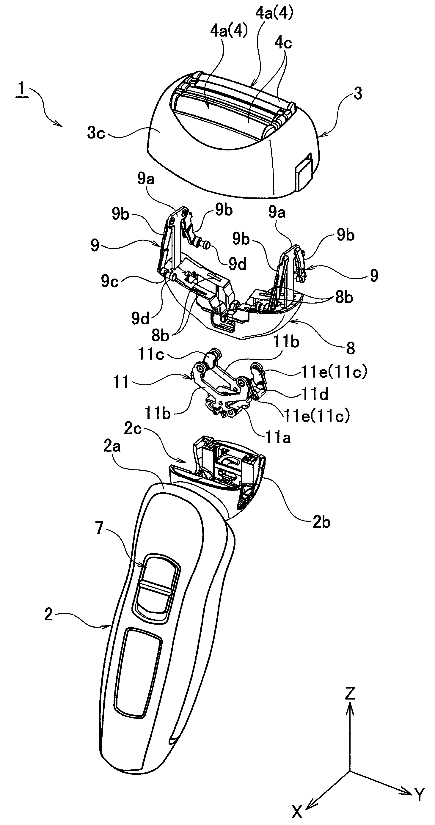
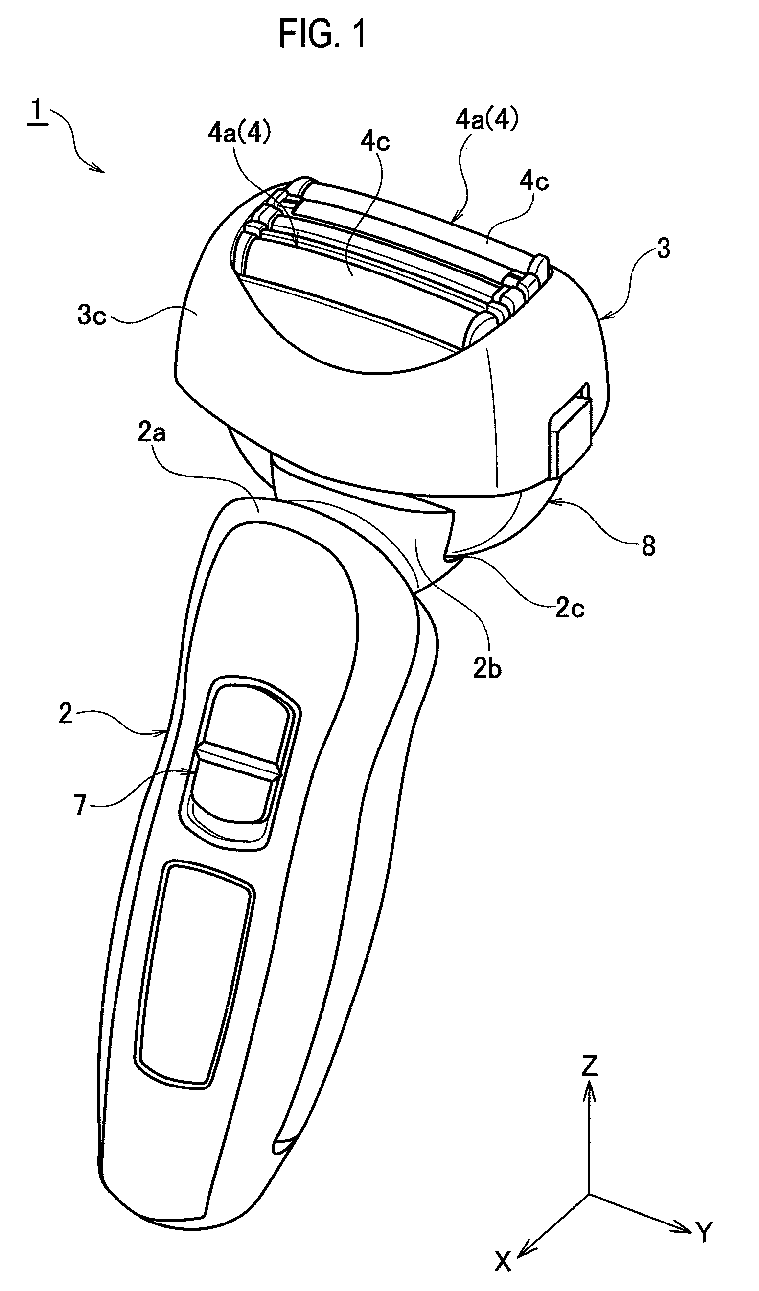
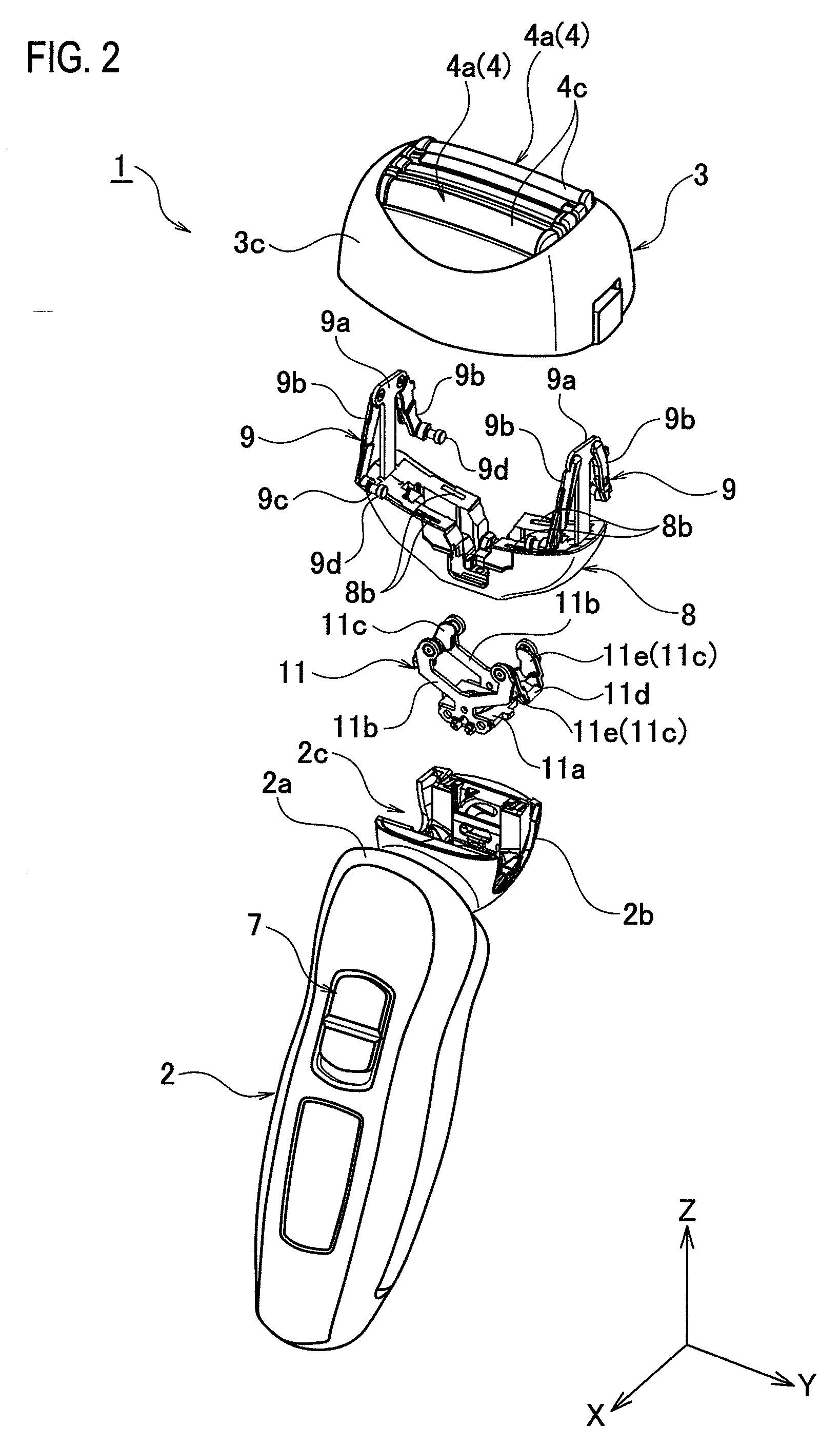
An electric shaver includes a rod-shaped body part, a head part, and a link mechanism. The head part projects from one end portion, in a longitudinal direction, of the body part and is swingably attached to the body part with a support base between the body part and the head part. The head part includes a shaving portion and a drive mechanism. The shaving portion is formed to be elongated in a direction orthogonal to a projecting direction of the head part and has paired blades configured to operate relative to each other. The drive mechanism is configured to drive at least one of the paired blades. The link mechanism includes two link arms each connected to the support base and the head part respectively at connecting axes parallel to a longitudinal direction of the shaving portion. The link mechanism is configured to support the head part on the support base swingably. The two link arms are disposed asymmetrically with respect to a straight line passing on a center of gravity of the head part and extending parallel with the projecting direction of the head part, when viewed in the longitudinal direction of the shaving portion.

Description

CROSS REFERENCE TO RELATED APPLICATION[0001]This application is based upon and claims the benefit of priority from the prior Japanese Patent Application No. 2009-006274, filed on Jan. 15, 2009, the entire contents of which are incorporated herein by reference.BACKGROUND OF THE INVENTION[0002]1. Field of the Invention[0003]The present invention relates to an electric shaver.[0004]2. Description of the Related Art[0005]Japanese Patent Application Laid-Open Publication No. Hei 6-343776 discloses an electric shaver in which a head part having elongated shaving portions is attached to a tip portion of a substantially rod-shaped body part swingably about two swing axes orthogonal to each other.SUMMARY OF THE INVENTION[0006]To shave one's cheeks, for example, an electric shaver of this kind is used in a horizontal position. When the electric shaver is in such horizontal position, the gravity acting on the head part allows the head part to swing downward easily, but not to swing upward easi...

Claims


Application Information

Patent Timeline
IPC IPC(8): B26B19/02B26B19/28
CPCB26B19/28B26B19/048
Inventor SHIMIZU, HIROAKISHIGETA, HIROSHIHOSOKAWA, SHINIWASAKI, JYUZAEMON
Owner PANASONIC CORP
Why Eureka
Try Eureka