Light emitting apparatus, liquid crystal display apparatus and lighting apparatus

a technology of liquid crystal display and light emitting apparatus, which is applied in the direction of discharge tube luminescnet screen, discharge tube/lamp details, instruments, etc., can solve the problems of difficult uniform mixing of two kinds of fluorescent materials in resin materials, disadvantages in emission efficiency, and more characteristic light closer to that of natural white light that cannot be emitted, etc., to achieve easy adjustment, easy setting, and advantage in emission efficiency of the apparatus

Inactive Publication Date: 2006-11-16
SHARP KK
View PDF5 Cites 10 Cited by
  • Summary
  • Abstract
  • Description
  • Claims
  • Application Information

AI Technical Summary

Benefits of technology

[0020] The present invention is intended to solve the problems described above. The objective of the present invention is to provide a light emitting apparatus capable of emitting an arbitrary natural light along the characteristic curve of black-body radiation, with which it is easy to control the balance of each color intensity, the light emitting apparatus having advantages in emission efficiency and in capability to mass-produce; a liquid crystal display apparatus mounted on an electronic information device using the light emitting apparatus as a backlight of a liquid crystal display screen; and a lighting apparatus using the light emitting apparatus as a light source.
[0040] In this case, the light emitted from the fluorescent material can be controlled by controlling light of the two wavelength components emitted from the semiconductor light emitting element. Thus, there is no need to control three wavelengths or four wavelengths of the primary colors simultaneously, as was conventionally required. Therefore, it is easier than was conventionally possible to control each color component so as to be set at an arbitrary color temperature on the characteristic curve of black-body radiation. When the content of the fluorescent material contained in a resin and the thickness of the resin having the fluorescent material contained therein are adjusted, the resulting light emitted from the combination of the three wavelength components of the light emitted from the semiconductor light emitting element and the wavelength component of the light emitted from the fluorescent material is easily adjusted. Thus, the combined light can be easily set at an arbitrary color temperature on the characteristic curve of black-body radiation.
[0041] Furthermore, there is an advantage in emission efficiency of the apparatus in the present invention when compared to the absorption and emission of two wavelength components which are observed in conventional apparatuses since only one kind of fluorescent material is used in the apparatus of the present invention. Also, there is no need to uniformly mixing two kinds of fluorescent materials in a resin material as was required with the conventional apparatuses. Thus, the difference in color intensity between each fluorescent color produced does not occur. Therefore, the problem in achieving the mass production capability, which occurs with conventional apparatuses, is solved by the present invention.
[0042] As described above, the present invention can easily control the balance of each color intensity and has an advantage in emission efficiency and in capability to mass-produce. Also, the present invention can emit an arbitrary natural light along the characteristic curve of black-body radiation.

Problems solved by technology

As a result, light having more characteristics which are closer to that of natural white light cannot be emitted.
In the methods disclosed in (3), (5) and Reference 2, there is a disadvantage in emission efficiency since absorption and emission of two wavelengths occur between two kinds of fluorescent materials.
Furthermore, it is difficult to uniformly mix the two kinds of fluorescent materials in a resin material due to differences in specific gravity of each of the fluorescent materials.
Therefore, a problem occurs in that it is difficult to mass-produce.

Method used


Image

  • Light emitting apparatus, liquid crystal display apparatus and lighting apparatus
  • Light emitting apparatus, liquid crystal display apparatus and lighting apparatus
  • Light emitting apparatus, liquid crystal display apparatus and lighting apparatus

Examples


Embodiment Construction

[0047] Hereinafter, an embodiment of a light emitting apparatus according to the present invention will be described with reference to the accompanying drawings.

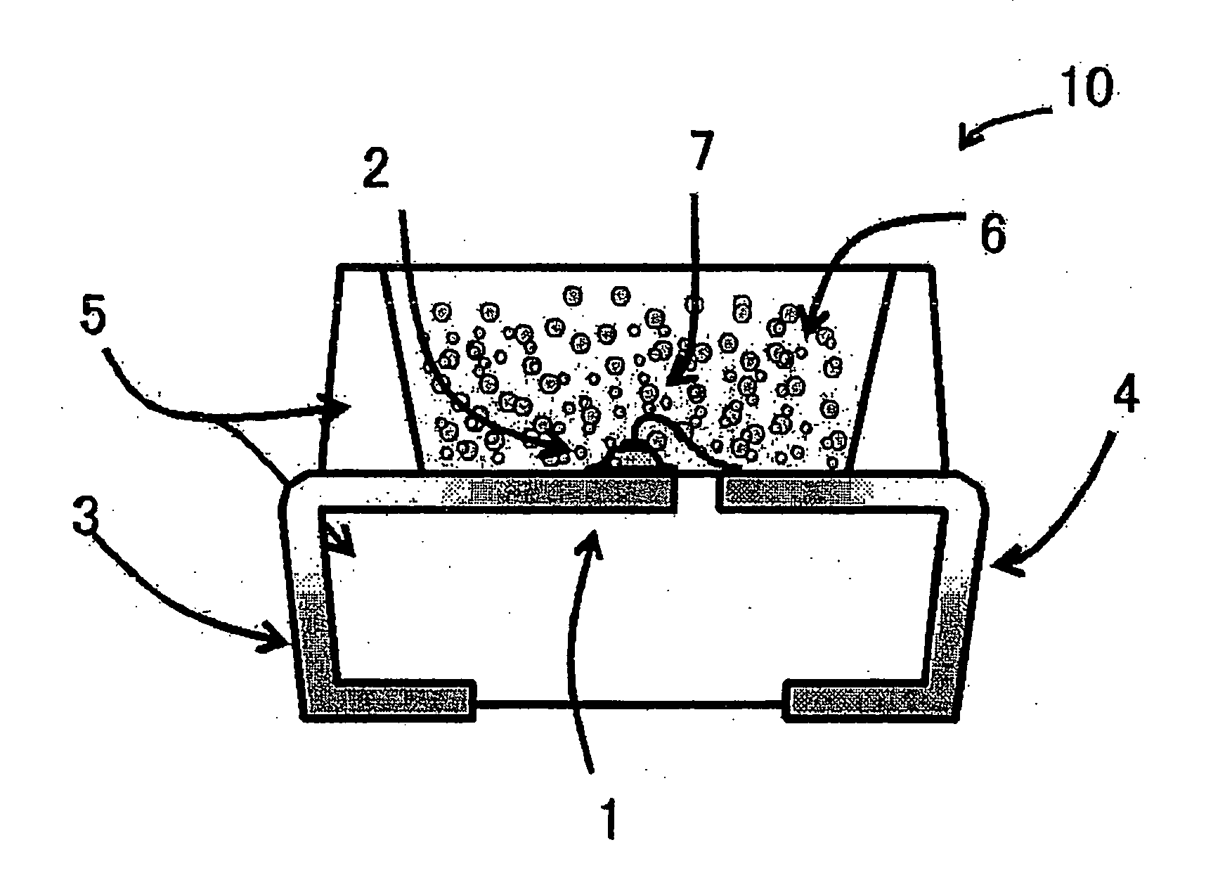
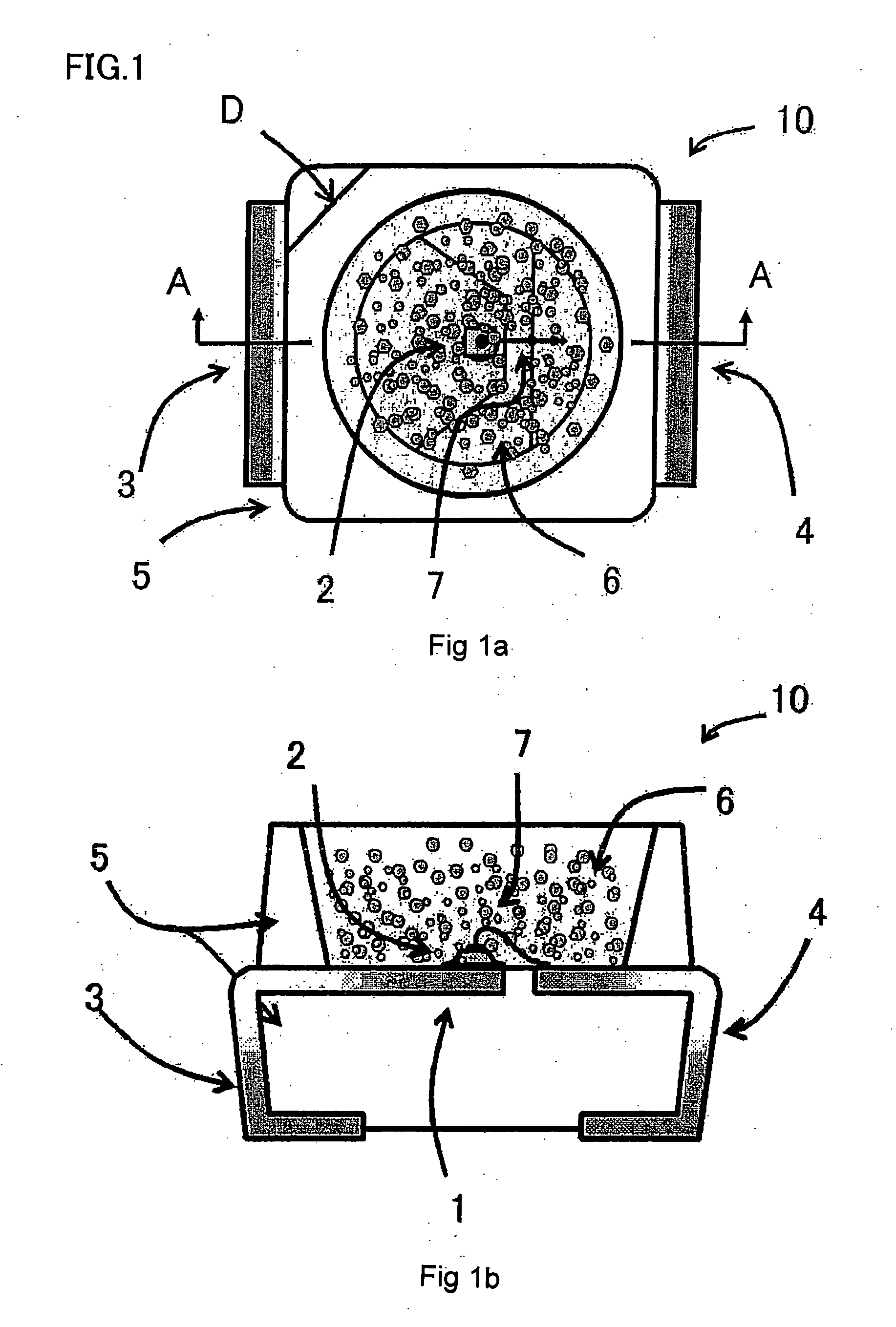
[0048]FIG. 1 is a diagram showing a structure of the light emitting apparatus according to the embodiment of the present invention. (a) is a plain view thereof. (b) is a cross-sectional view of (a) cut by A-A′ line.

[0049] In FIGS. 1(a) and 1(b), a light emitting apparatus 10 according to the present embodiment has an LED chip 2 provided on a metal base frame 1. Each terminal of the LED chip 2 is connected to an anode terminal 3 and a cathode terminal 4, respectively. The anode terminal 3 and the cathode terminal 4 are a part of the metal frame and protrude out from a resin case 5. The base frame 1 is integrated with the anode terminal 3. At the frontal side of a light-emitting face (upward direction of opening side of a concaved portion) of the LED chip 2 provided at the bottom of the concaved portion in the center of the ...


PUM


Abstract

A light emitting apparatus includes: a semiconductor light emitting element capable of emitting light of two wavelength components; and a fluorescent material section, having a fluorescent material contained therein, capable of emitting light, the light being radiated as a result of fluorescence from the fluorescent material when the fluorescent material is excited by the two wavelength components, wherein the two wavelength components and the wavelength component resulting from the fluorescence are adjusted so as to be set at an arbitrary color temperature on a characteristic curve of black-body radiation.

Description

[0001] This Nonprovisional application claims priority under 35 U.S.C. §119(a) on Patent Applications No. 2005-121465 filed in Japan on Apr. 19, 2005, the entire contents of which are hereby incorporated by reference. BACKGROUND OF THE INVENTION [0002] 1. Field of the Invention [0003] The present invention relates to: a light emitting apparatus used for obtaining white light using a fluorescent material which wavelength-converts light emitted from a light emitting diode (LED) as a semiconductor light emitting element; a liquid crystal display apparatus mounted on an electronic information device (e.g., a liquid crystal television apparatus, a personal computer, a PDA (personal display association) and a cellular phone) using the light emitting apparatus as a backlight of a liquid crystal display screen; and a lighting apparatus in doors or out of doors using the light emitting apparatus as a light source. [0004] 2. Description of the Related Art [0005] Conventionally, the light emit...

Claims


Application Information

Patent Timeline
Patent Type & Authority Applications(United States)
IPC IPC(8): H01J63/04H01J1/62H01L33/50
CPCC09K11/0883C09K11/665C09K11/7728C09K11/7789C09K11/7794G02F1/133603H01L2924/0002H01L25/0756H01L33/50H05B33/14H01L2924/00
Inventor MASUDA, MASATSUGUUMEDA, HIROSHIKITANO, MASAHARUOOUCHIDA, TAKASHI
Owner SHARP KK
Why Eureka
Try Eureka