
Liquid droplet ejection control apparatus and liquid droplet ejecting apparatus

Inactive Publication Date: 2010-03-25
FUJIFILM CORP
View PDF4 Cites 10 Cited by
  • Summary
  • Abstract
  • Description
  • Claims
  • Application Information

AI Technical Summary

Benefits of technology

[0009]The present invention has been made in consideration of the above-described circumstances and provides a liquid droplet ejection control apparatus and a liquid droplet ejecting apparatus that can easily perform, with a simple configuration, setting of identification information with respect to a plurality of head control units that control the ejection of liquid droplets by a liquid droplet ejecting head.

Problems solved by technology

However, the work of writing identification information that identifies the control boards in ROMs or the like beforehand and setting the identification information by setting switches takes effort.
Further, it is also easy for setting mistakes to occur.

Method used


Image

  • Liquid droplet ejection control apparatus and liquid droplet ejecting apparatus
  • Liquid droplet ejection control apparatus and liquid droplet ejecting apparatus
  • Liquid droplet ejection control apparatus and liquid droplet ejecting apparatus

Examples


Embodiment Construction

[0029]Below, an embodiment of the present invention will be described in detail on the basis of the drawings.

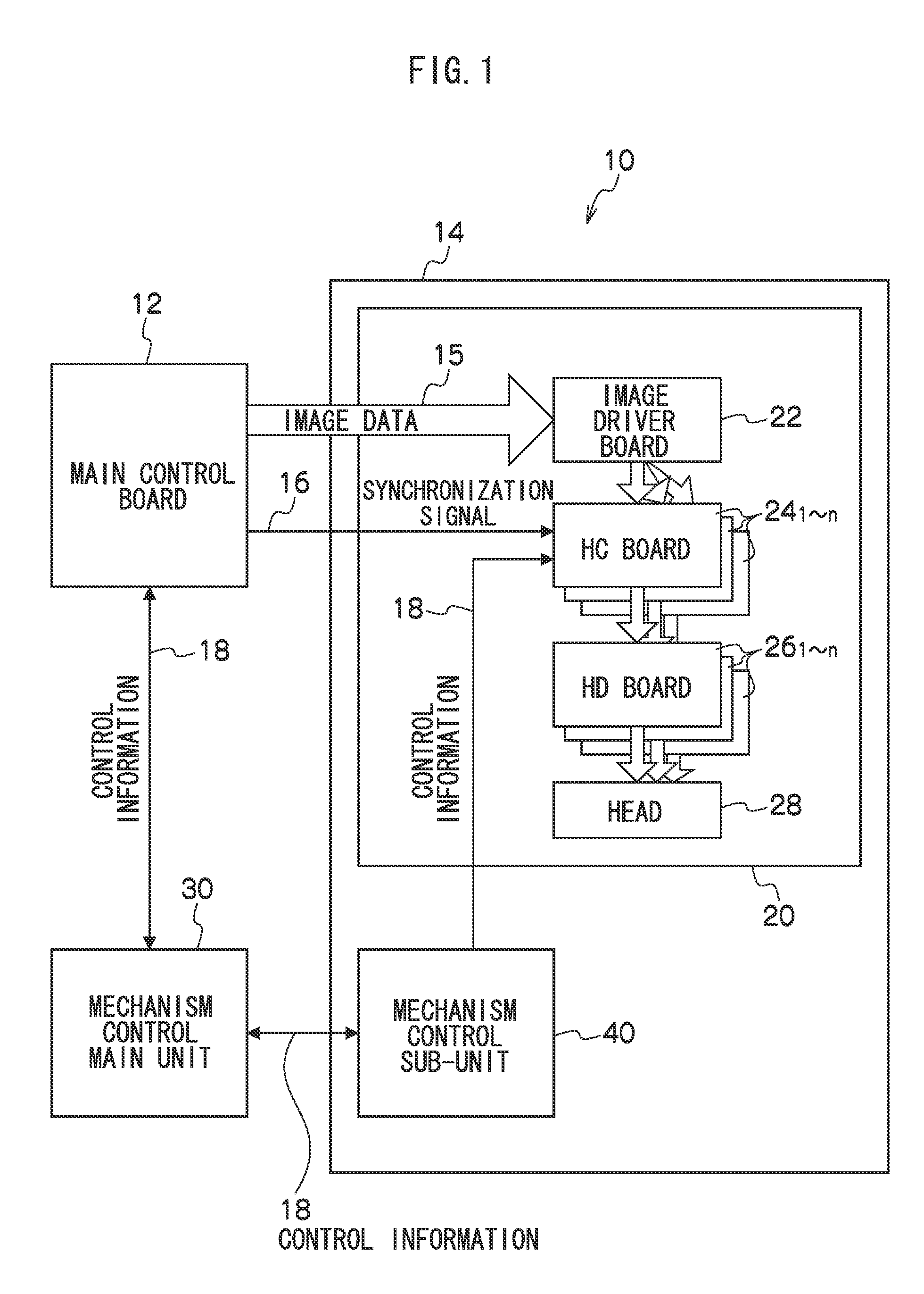
[0030]FIG. 1 is a diagram showing an example of the configuration of a liquid droplet ejecting apparatus 10 pertaining to the embodiment of the invention.

[0031]The liquid droplet ejecting apparatus 10 is equipped with a main control board 12, a head module 14 and a mechanism control main unit 30.

[0032]The main control board 12 is a board that is equipped with a CPU and various circuits that control the entire liquid droplet ejecting apparatus 10.

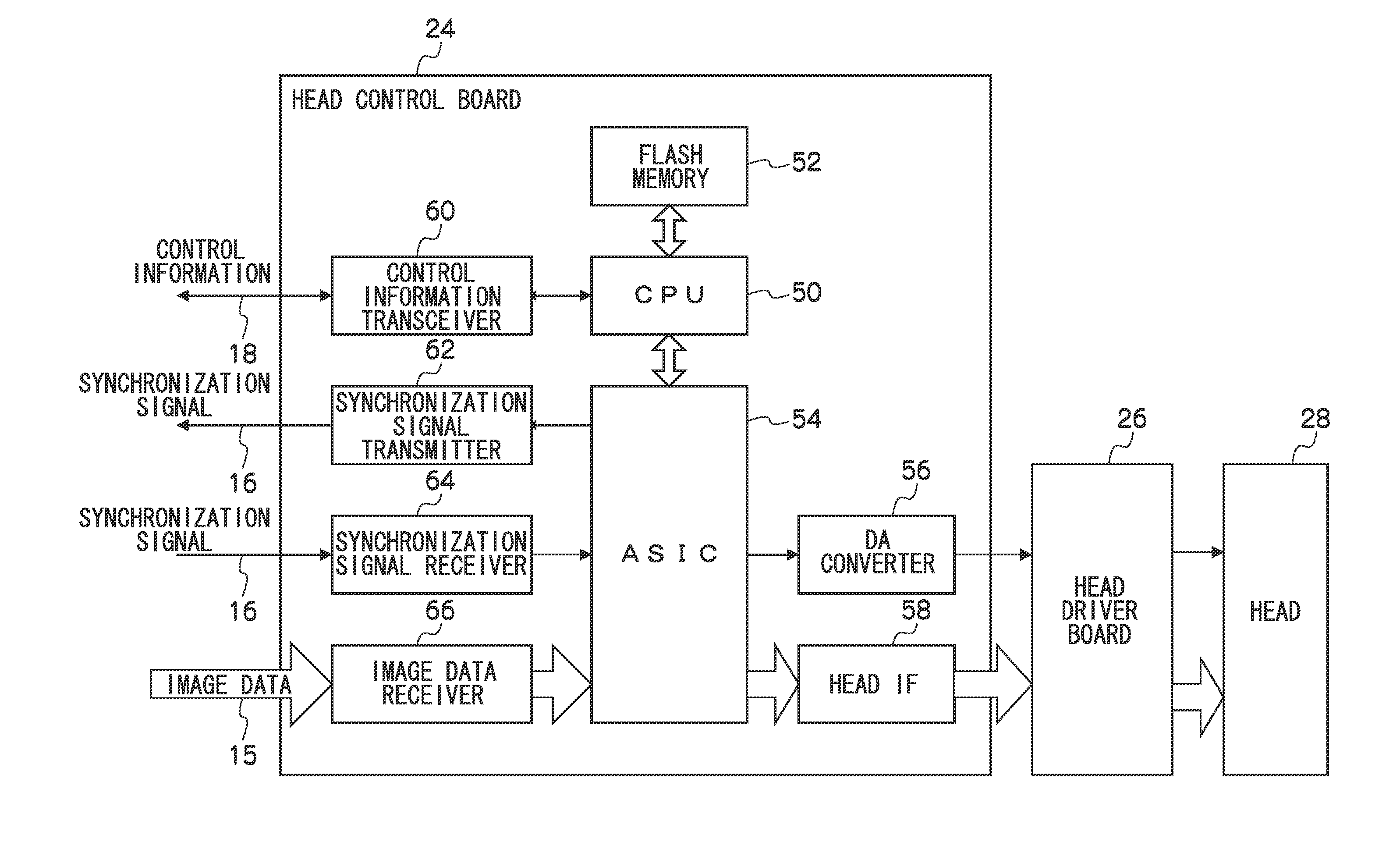
[0033]The head module 14 is equipped with a bar unit 20, in which a liquid droplet ejecting head 28 (hereinafter simply called “the head 28”) and control board groups of the head 28 are modularized, and a mechanism control sub-unit 40, which controls mechanisms around the head 28.

[0034]The mechanism control main unit 30 is a unit that includes boards that control mechanisms of the liquid droplet ejecting apparatus 10 other than those ...


PUM


Abstract

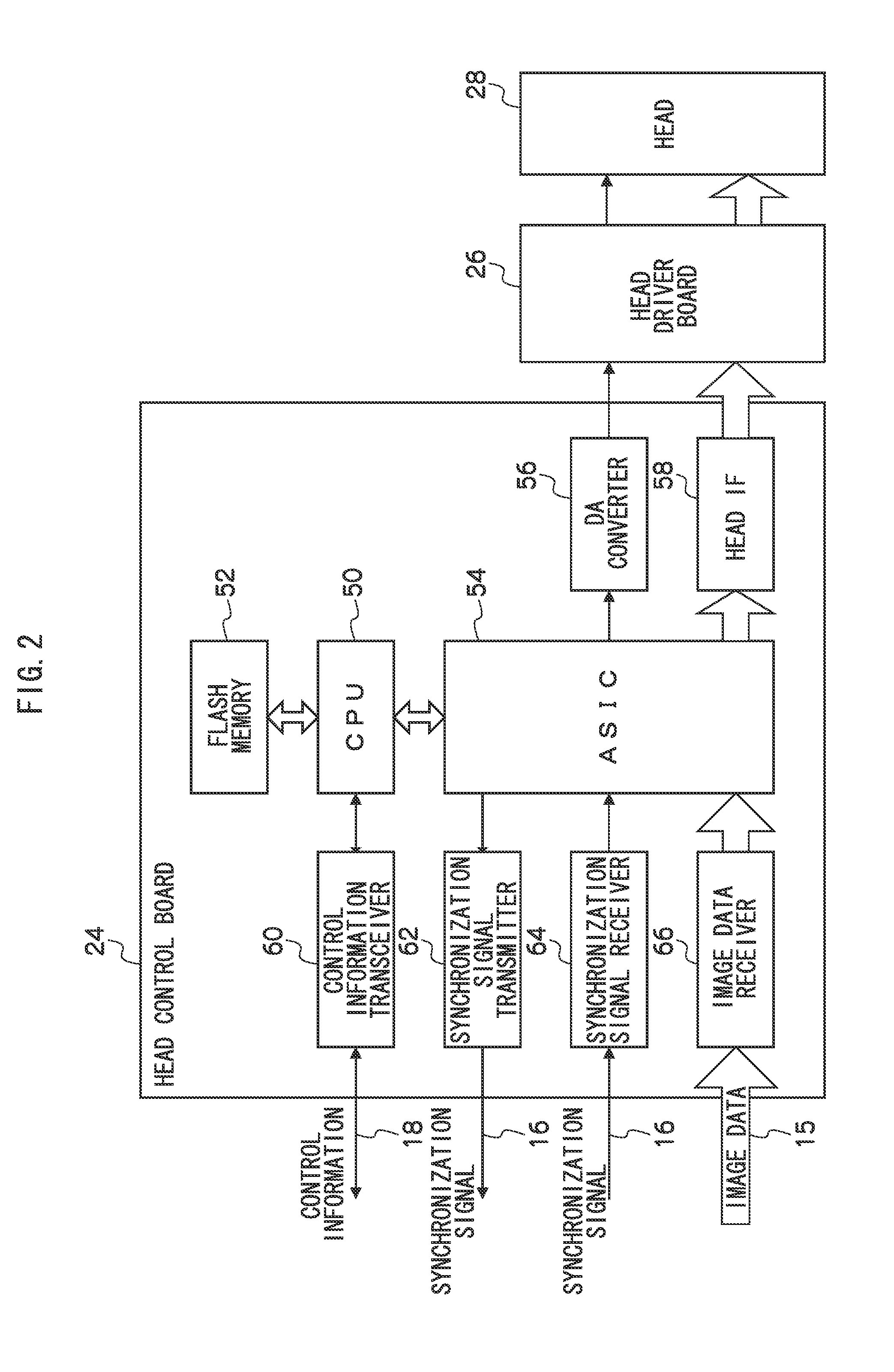
In a liquid droplet ejection control apparatus, a plurality of head control (HC) boards are disposed in correspondence to ejectors that eject liquid droplets and are plurally arrayed in a liquid droplet ejecting head, and the HC boards are connected to each other in a daisy chain by a synchronization signal line. Each of the HC boards is equipped with a memory for storing identification information. When an identification signal representing the identification information is superimposed on a synchronization signal received via the synchronization signal line from a prior stage, the identification information that the identification signal represents is stored in the memory, the identification signal superimposed on the received synchronization signal is changed so as to represent identification information different from the identification information that the identification signal represents, and the synchronization signal on which the changed identification signal has been superimposed is transmitted to a later stage.

Description

CROSS-REFERENCE TO RELATED APPLICATION[0001]This application claims priority under 35 USC 119 from Japanese Patent Application No. 2008-244511 filed on Sep. 24, 2008, the disclosure of which is incorporated by reference herein.BACKGROUND OF THE INVENTION[0002]1. Field of the Invention[0003]The present invention pertains to a liquid droplet ejection control apparatus and a liquid droplet ejecting apparatus and particularly relates to a liquid droplet ejection control apparatus and a liquid droplet ejecting apparatus disposed with head control units in which identification information is set.[0004]2. Description of the Related Art[0005]Liquid droplet ejecting apparatus that are disposed with a head in which nozzles that eject liquid droplets are plurally arrayed and which eject the liquid droplets onto a recording medium are known. Liquid droplet ejecting apparatus where plural control boards are disposed in correspondence to the plural nozzles arrayed in the head and where the head i...

Claims


Application Information

Patent Timeline
IPC IPC(8): B41J29/38
CPCB41J2/04508B41J2/04586B41J2/04573
Inventor YOKOTA, KENJI
Owner FUJIFILM CORP
Learn More