
Mobile communications system, base station, and mobile terminal

Active Publication Date: 2010-07-15
TCL COMM TECH HLDG
View PDF13 Cites 80 Cited by
  • Summary
  • Abstract
  • Description
  • Claims
  • Application Information

AI Technical Summary

Benefits of technology

[0039]The mobile communications system in accordance with the present invention notifies the presence or absence of emergency information to the mobile terminal with the description of the flag disposed in the control channel for the broadcast type multimedia service and showing the presence or absence of emergency information. Therefore, the mobile communications system can notify emergency information to the mobile terminal by using the broadcast type multimedia service which provides a large amount of deliverable information without imposing an excessive load on a mobile communications network and without impairing the immediacy of the emergency information.

Problems solved by technology

However, this nationwide instantaneous alert system using speakers to notify, by voice, emergency information causes a case in which those who live in an area distant from the speakers and so on cannot know the emergency information.
There is a risk of collision.
Because conventional mobile communications systems are constructed as mentioned above, a problem with them is that they are easily affected by the influence of the load on the communications line when they are used as a system for broadcasting emergency information to an indefinite number of users, the area in which emergency information can be delivered is narrow, and the immediacy of the information may be impaired.
Therefore, because the service depends upon the capacity of the communications line between the base station and the mobile terminals, there occurs a case in which the load on the communications line increases and therefore the conventional system cannot notify emergency information to the mobile terminals when the number of users to whom the conventional system notifies the emergency information increases.
Therefore, the conventional system is not suitable for notification of emergency information to an indefinite number of users.
Furthermore, in a conventional system that notifies emergency information by using digital terrestrial broadcasting, as compared with a system using a mobile communications network, there are many locations where the receiving characteristics of digital terrestrial broadcasting waves degrade, such as an indoor, the shade of a building, and an underground shopping area, and there may be a case in which emergency information cannot be broadcast precisely.
In addition, because it is necessary to add hardware used for receiving digital terrestrial broadcasting to each mobile terminal, the conventional system has a demerit for the downsizing and low pricing of mobile terminals.
However, when a base station broadcasts data to mobile terminals, all of the mobile terminals cannot receive the transmission data and only mobile terminals in an idle (Idle) state can receive the transmission data.
Therefore, the short message defined for the CBS does not have a data amount enough to notify emergency information, such as map information or picture information, according to the needs of users.
In addition, in the system disclosed by patent reference 1, because channel information for receiving the emergency information and the identifier of the emergency information have to be added to broadcast information as parameters, the amount of information which should be transmitted as the broadcast information increases unavoidably.
Therefore, it is also expected that the use of the method of adding the parameters for transmitting emergency information to broadcast information causes a necessity to limit the data amount of the parameters for transmitting emergency information in consideration of the amount of information to be transmitted as the broadcast information, and an excessive increase in the amount of information of the broadcast information to which the parameters are added.
A problem with a conventional mobile communications system which performs an MBMS is, however, that the conventional mobile communications system can deliver multimedia information to a plurality of users' mobile terminals simultaneously, while each user side cannot receive provision of any information unless it initiatively receives an MTCH on which desired data are carried, and therefore the immediacy of emergency information may be impaired.

Method used


Image

  • Mobile communications system, base station, and mobile terminal
  • Mobile communications system, base station, and mobile terminal
  • Mobile communications system, base station, and mobile terminal

Examples


embodiment 1

[0060]In accordance with this Embodiment 1, an emergency information flag (an emergency information indicator) indicating the presence or absence of emergency information is disposed in an MCCH which is an MBMS control channel, and a mobile terminal is enabled to check the presence or absence of the emergency information at regular intervals. Accordingly, even while receiving information other than the emergency information by using an MBMS, the mobile terminal can recognize the existence of the emergency information by using the emergency information flag, and can receive an emergency information channel included in the MBMS.

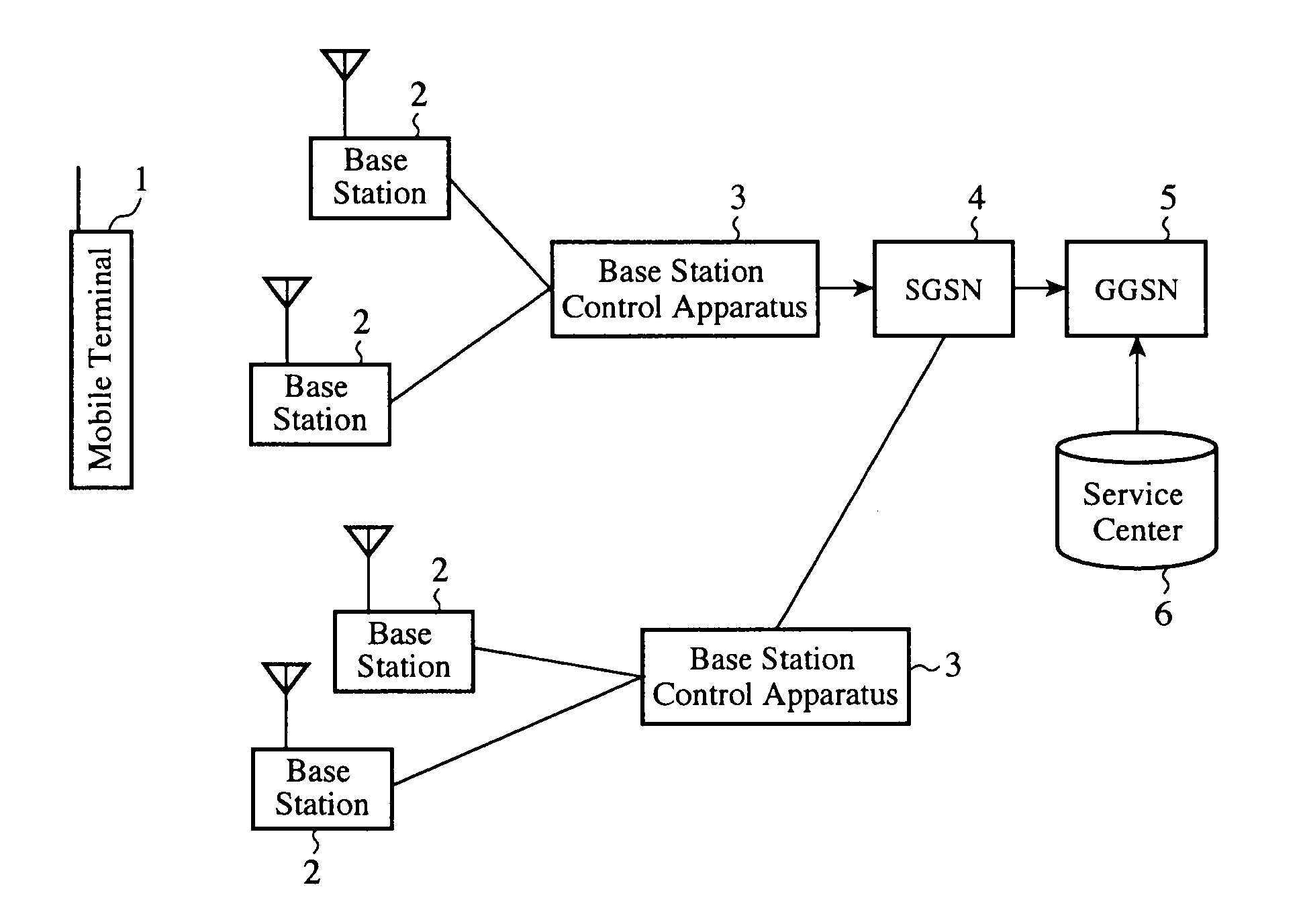
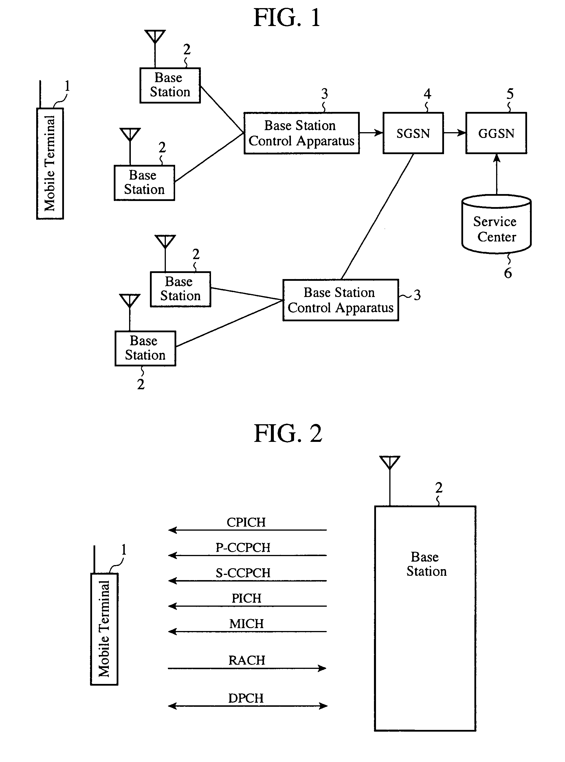
[0061]FIG. 1 is a diagram showing the structure of a mobile communications system in accordance with the present invention. In this system, emergency information is notified to all mobile terminals 1 which support the MBMS by using the MBMS. In FIG. 1, the mobile communications system in accordance with the present invention is provided with mobile terminals 1,...

embodiment 2

[0131]A mobile communications system in accordance with this Embodiment 2 notifies the occurrence of emergency information to even a mobile terminal which is communicating individual data, such as data about a voice call or packets, but is not receiving any MBMS data, thereby enabling the mobile terminal to receive an emergency information channel included in an MBMS.

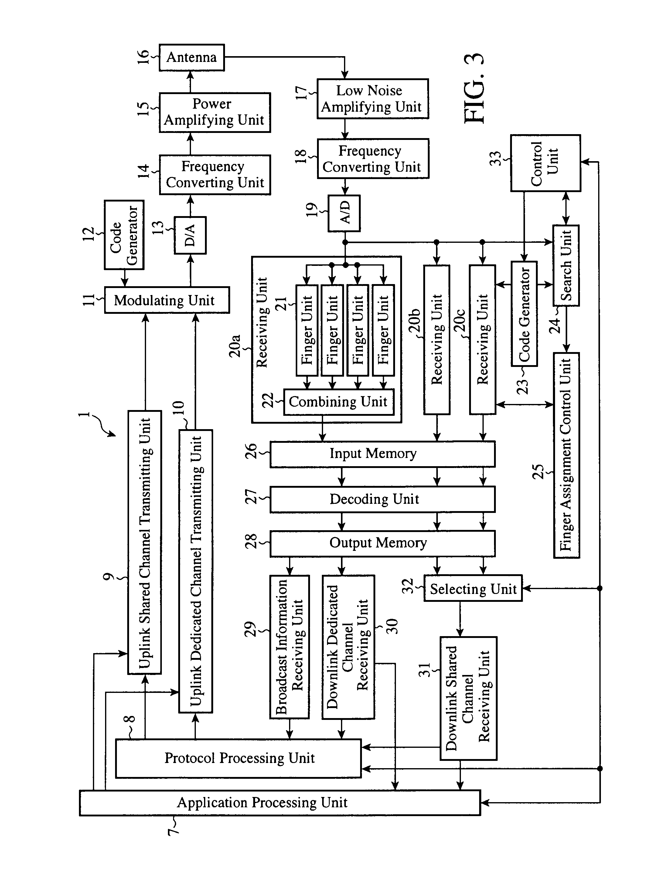
[0132]Although the fundamental structures of each mobile terminal, each base station, and each base station control apparatus which are disposed in the mobile communications system in accordance with Embodiment 2 are the same as those according to above-mentioned Embodiment 1 shown in FIGS. 1 to 5, they differ from those of Embodiment 1 in that when emergency information occurs, each base station transmits an MICH to mobile terminals before transmitting an MCCH, and a mobile terminal which is communicating individual data, such as data about a voice call or packets, but is not receiving any MBMS data receives the MCCH a...

embodiment 3

[0154]A mobile communications system in accordance with this Embodiment 3 is constructed in such a way as to notify the occurrence of emergency information to even a mobile terminal placed in an idle state in which it is not receiving any MBMS data to enable the mobile terminal to receive an emergency information channel included in an MEMS.

[0155]Although the fundamental structures of each mobile terminal, each base station, and each base station control apparatus which are disposed in the mobile communications system in accordance with Embodiment 3 are the same as those according to above-mentioned Embodiment 1 shown in FIGS. 1 to 5, they differ from those of Embodiment 1 in that when emergency information occurs, each base station transmits an MICH to mobile terminals before transmitting an MCCH, and a mobile terminal placed in an idle state in which it is not receiving any MBMS data receives the MCCH according to the description of the indicator of the MICH, and then determines t...


PUM


Abstract

A mobile communications system including a mobile terminal 1 and a base station 2 which relays communications between a network and the mobile terminal 1, in which the base station 2 can deliver information to the mobile terminal 1 by using an MBMS, in which the base station 2 sets a flag indicating presence or absence of emergency information to a control channel used for the MBMS, and notifies the presence or absence of the emergency information to the mobile terminal 1 by using the description of the flag set to the control channel for the MBMS.

Description

FIELD OF THE INVENTION[0001]The present invention relates to a mobile communications system that can notify emergency information by using a broadcast type multimedia service, and a base station and a mobile terminal which construct this mobile communications system.BACKGROUND OF THE INVENTION[0002]Recent years have seen growing social needs for a system which, in the event of occurrence of an emergency situation, such as an earthquake or a tsunami, can notify emergency information about the emergency to many people immediately. On the other hand, the market size of mobile terminals, such as mobile phones, is increasing year by year. In Japan, the market size has reached more than 90 million sets of mobile terminals and there occur social circumstances in which many persons own a mobile phone. Therefore, information delivery using mobile terminals via a mobile communications network can be made to serve as an effective notifying means of notifying emergency information.[0003]As a sy...

Claims


Application Information

Patent Timeline
IPC IPC(8): H04M11/04H04W4/90
CPCH04W4/06H04W76/007H04W4/22H04W4/90H04W76/50H04W68/00
Inventor MAEDA, MIHOTADA, KEIKOTAKAHASHI, YOSHINORINAKAMIZO, HIDEYUKITAKAHASHI, KAZUNORIITOH, TATSUYAMOCHIZUKI, MITSURU
Owner TCL COMM TECH HLDG
Learn More