Method and apparatus for controlling uplink transmission power

a transmission power and transmission power technology, applied in the field of transmission power control methods, can solve the problems that the power control algorithm and the general cas lack the ability to guarantee the performance of the dmns, and achieve the effect of accurate downlink channel characteristics, accurate uplink transmission power, and reduced calculation complexity of the terminal in calculating uplink transmission power

Inactive Publication Date: 2014-12-23
LG ELECTRONICS INC
View PDF20 Cites 207 Cited by
  • Summary
  • Abstract
  • Description
  • Claims
  • Application Information

AI Technical Summary

Benefits of technology

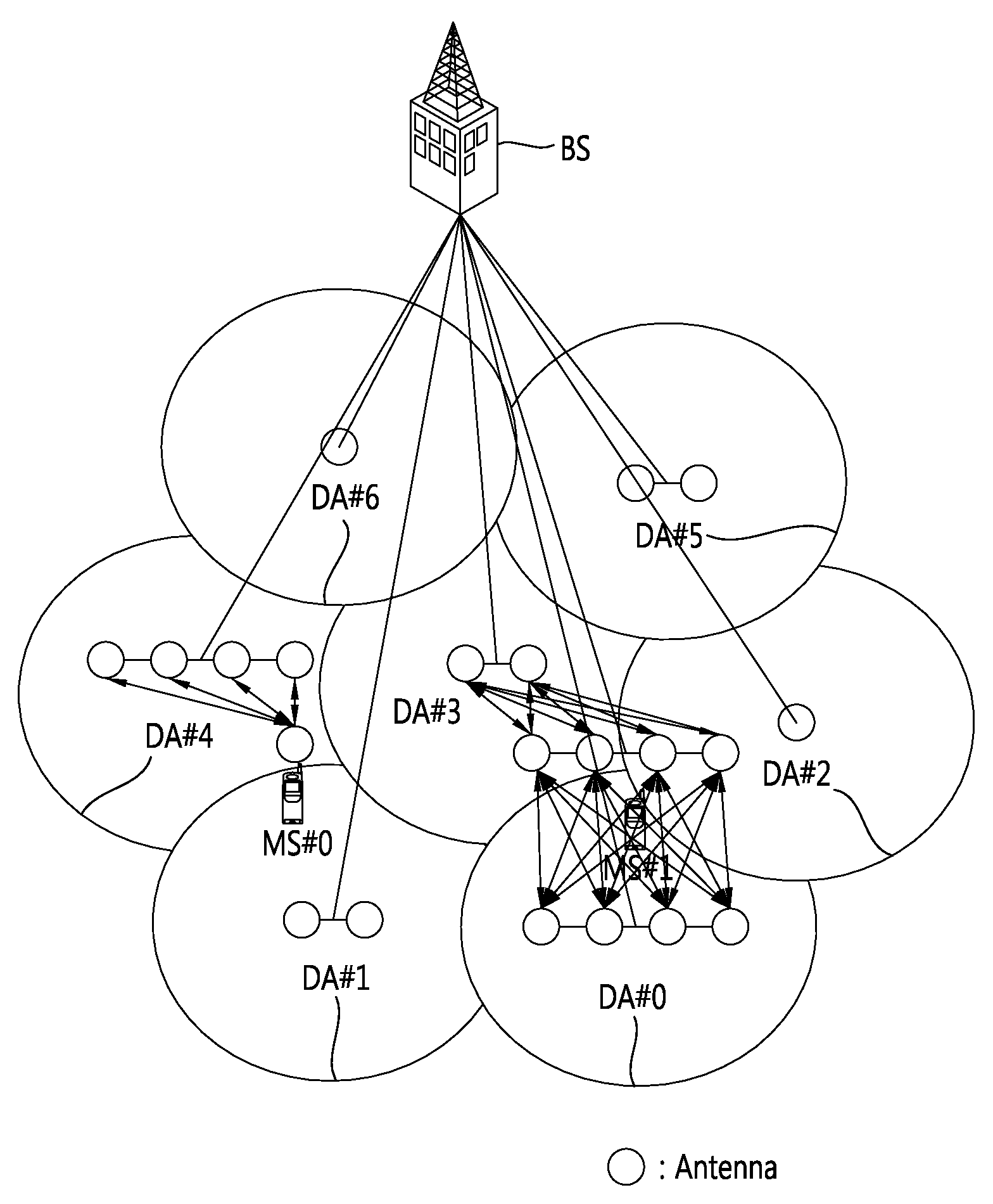
[0057]According to embodiments of the present invention, in the DMNS, information regarding antenna nodes (DA) included in a BS or antenna nodes to be measured by a terminal is transmitted to the terminal, whereby accurate uplink transmission power can be determined and calculation complexity of the terminal in calculating uplink transmission power can be reduced.
[0058]Also, according to embodiments of the present invention, by estimating accurate downlink channel characteristics between respective antenna nodes and a terminal and noise and interference received from the respective antenna nodes, accurate uplink transmission power of the terminal can be determined.
[0059]Also, according to embodiments of the present invention, when uplink transmission power of a terminal is determined, a difference between downlink reception power and uplink reception power is reflected, thus determining accurate uplink transmission power of the terminal.

Problems solved by technology

As described above, the CAS and the DMNS have different antenna configurations and different channel characteristics due to the different antenna configurations, and thus, an existing power control algorithm and mechanism designed for the general CAS lack ability to guarantee performance in the DMNS.

Method used


Image

  • Method and apparatus for controlling uplink transmission power
  • Method and apparatus for controlling uplink transmission power
  • Method and apparatus for controlling uplink transmission power

Examples


first embodiment

[0117

[0118]In general, when a mobile station (MS) is connected to a BS via a network, the MS may receive BS antenna information from the BS or obtain BS antenna information through detection of downlink control information.

[0119]Next, the MS measures RSRP, RSSI, and the like, thereof with respect to the BS by using a reference signal with respect to each cell such as a preamble of a downlink frame or MIMO mid-amble, a CRS (Cell-specific Reference Signal), CSI-RS (Channel State Information Reference Signal), and the like, and estimates a propagation loss (path loss).

[0120]The MS may calculate uplink transmission power with respect to target SINR, Target IoT, and the like, by using information regarding a noise and interference level (NI) along with the afore-mentioned information.

[0121]In a DMNS, respective antenna nodes are installed in a distributed manner, so link characteristics between the respective antenna nodes and the MS may be much different. Thus, if a downlink channel is ...

second embodiment

[0152

[0153]A second embodiment of the present disclosure provides a method for calculating uplink transmission power by measuring channel characteristics between respective DAs and a mobile station and determining the number of effective antenna nodes based on the measured channel characteristics in a distributed multi-node system (DMNS).

[0154]Also, the second embodiment of the present disclosure provides a method for calculating uplink transmission power by estimating power of a reference signal received from each DA or each antenna and noise and interference in the DMNS.

[0155]First, a method for determining an effective antenna and DA will be described.

[0156]Determining Effective Antenna and DA

[0157]When it is assumed that a mobile station can discriminate reception power in every antenna level, the mobile station may select an effective antenna by comparing reception power received from each antenna with an effective received power threshold (or an effective reception power level...

third embodiment

[0247

[0248]The third embodiment of the present disclosure provides a method of re-estimating a representative path loss with respect to the entire serving nodes by assigning weight to a downlink path loss estimated for each node.

[0249]Estimation of representative path loss through application of weight

[0250]It is assumed that when M number of nodes are uplink serving nodes with respect to a mobile station, a path loss of each node estimated by the mobile station is P(n)(n=1, . . . , M).

[0251]The mobile station re-estimates a representative path loss P with respect to the entire serving nodes by assigning a weight P(n)(n=1, . . . , M) to an estimated path loss (or an estimated propagation loss) for each node

[0252]P=10⁢⁢log⁢⁢10⁢(∑n=1M⁢w⁡(n)·10⋀⁢(P⁡(n)10))[dBm][Equation⁢⁢14]

[0253]Here, the weight w(n) may be determined by using at least any one of the following methods.

[0254]Method 1: Method of estimating, by a BS, a path loss based on an uplink reception power distribution of each nod...


PUM


Abstract

The present description relates to a method for controlling uplink power in a distributed multi-node system, comprising the following steps: receiving reference signals from a plurality of antenna nodes containing at least one antenna; estimating average propagation loss on the basis of the receiving power of the reference signals received from the plurality of antenna nodes; receiving, via a downlink control channel, noise and interference (NI) information from a base station which contains the plurality of antenna nodes; and determining uplink transmission power using the estimated average propagation loss and the received noise and interference information.

Description

CROSS-REFERENCE TO RELATED APPLICATIONS[0001]This application is the National Stage filing under 35 U.S.C. 371 of International Application No. PCT / KR2011 / 001606, filed on Mar. 8, 2011, which claims the benefit of earlier filing date and right of priority to Korean Patent Application No. 10-2011-0020580, filed on Mar. 8, 2011, and also claims the benefit of U.S. Provisional Application Ser. No. 61 / 311,746, filed on Mar. 8, 2010, U.S. Provisional Application Ser. No. 61 / 315,014, filed on Mar. 18, 2010, U.S. Provisional Application Ser. No. 61 / 381,445, filed on Sep. 10, 2010, U.S. Provisional Application Ser. No. 61 / 405,214, filed on Oct. 21, 2010 and U.S. Provisional Application Ser. No. 61 / 441,290, filed on Feb. 10, 2011, the contents of which are all hereby incorporated by reference herein in their entirety.TECHNICAL FIELD[0002]The present document relates to a method for controlling uplink transmission power and, more particularly, to a method and apparatus for controlling uplink ...

Claims


Application Information

Patent Timeline
Patent Type & Authority Patents(United States)
IPC IPC(8): G08C15/00H04W52/14H04L1/00H04J1/16H04L12/26G01R31/08G06F11/00G08C17/00H04B7/00H04J3/14H04W4/00
CPCH04W52/146H04B7/022H04B7/0417H04B7/0691H04W52/386H04W52/40H04W88/085H04B17/345
Inventor PARK, SUNGHOKANG, JIWONKIM, SUNAMIHM, BINCHULCHUN, JINYOUNGKIM, KITAEKIM, DONGCHEOL
Owner LG ELECTRONICS INC
Why Eureka
Try Eureka