Antenna system for producing variable-size beams

a variable-size beam and antenna technology, applied in direction finders, direction finders using radio waves, instruments, etc., can solve the problems of reducing reliability, no medium or middle beam size setting, and limited power handling capability of the system

Inactive Publication Date: 2008-01-01
LOCKHEED MARTIN CORP
View PDF21 Cites 20 Cited by
  • Summary
  • Abstract
  • Description
  • Claims
  • Application Information

AI Technical Summary

Benefits of technology

[0011]The phase controllers are controlled to set phases at the inputs of the hybrid matrix to provide proper relative power among the element sets required to achieve a desired beam size. The input signal phases may be incremented by equal phase shift values to vary the beam size.

Problems solved by technology

However, this antenna system is constrained to large and small beams only, and provides no medium or middle beam size setting because a beam size cannot be continuously varied.
In addition, power handling capability of the system is limited by a single feed element.
Such a mechanism reduces reliability and increases weight of the system.
Moreover, the system is restricted to beams of a circular nature.
There are several significant drawbacks to this approach.
Further, this concept is limited to arrays, which can be properly excited when the power from each coupler is directed into elements which are uniformly interleaved with elements driven from the other couplers.
This element interleaving constraint is necessary to work within the limitation of the subarray couplers, which is that the input power to any coupler can only be directed into a single output or into two outputs independently.
Power cannot be directed to 3 coupler outputs, and when power is directed to 4 outputs from any given coupler, the amplitudes cannot be controlled independently.
Moreover, this concept is limited to excitation of linear or radial arrays and does not allow a beam to be varied in two dimensions.

Method used


Image

  • Antenna system for producing variable-size beams
  • Antenna system for producing variable-size beams
  • Antenna system for producing variable-size beams

Examples


Embodiment Construction

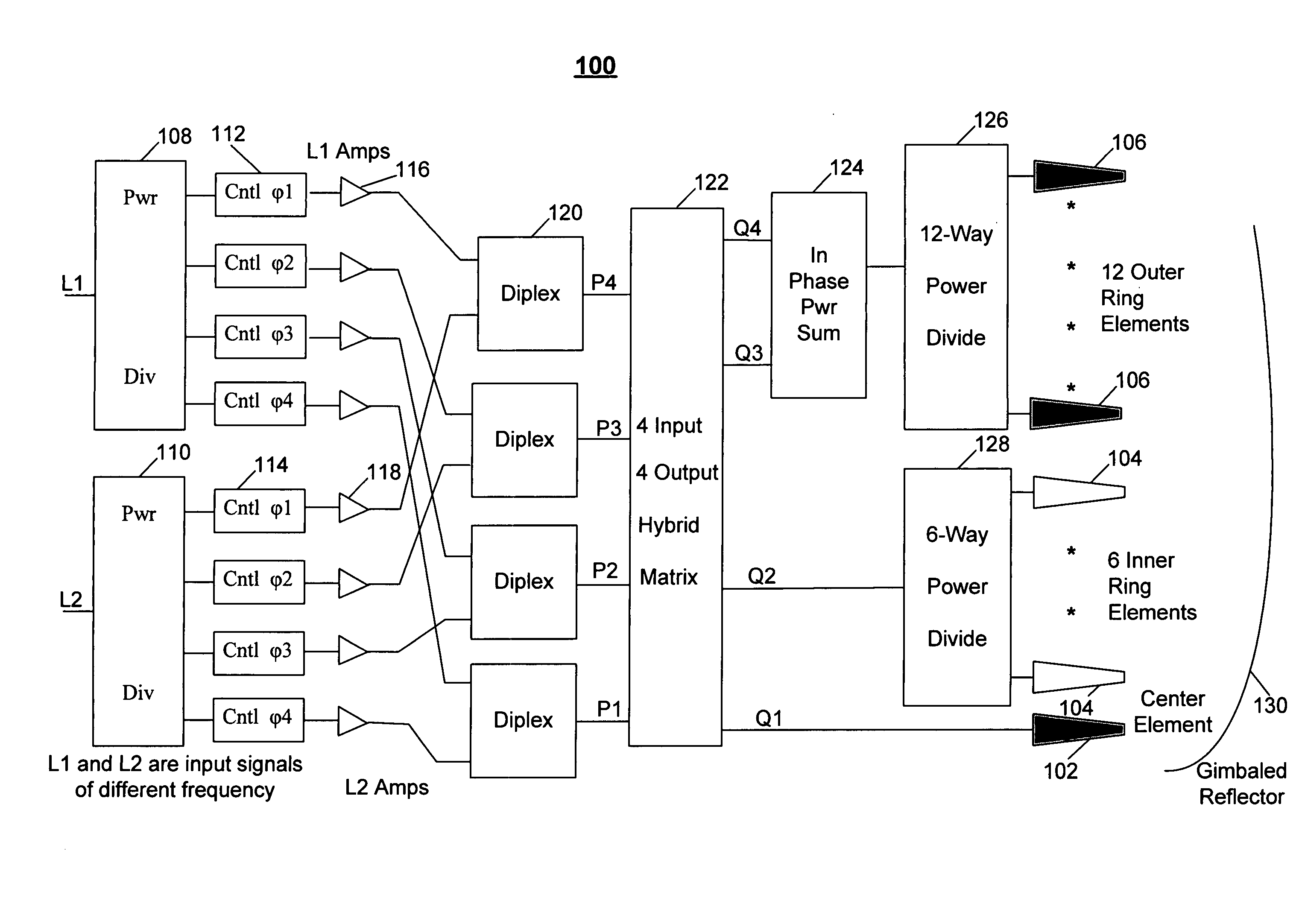
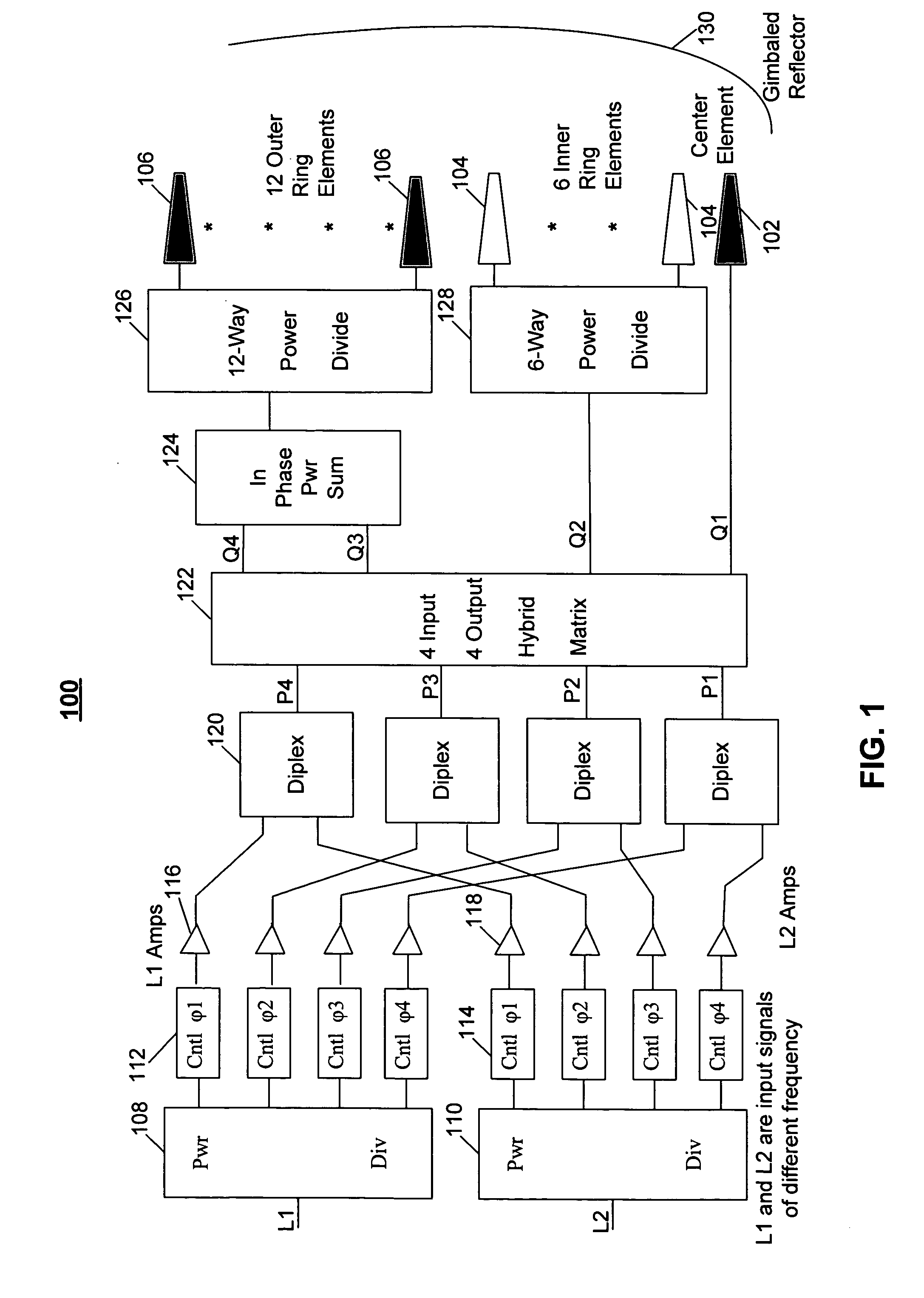
[0026]FIG. 1 is a block diagram of an exemplary antenna system 100 according to the invention. The system 100 can be used in a number of different applications including a global positioning system (GPS), a satellite communications system, a radar system, etc. Although FIG. 1 shows that the system 100 operates at two frequencies L1 and L2 appropriate for the GPS (e.g. L1=1575,42 MHz, L2=1227,5 MHz), one skilled in the art would realize that the antenna system of the present invention is able to operate at a single frequency as well as at any number of various frequencies.

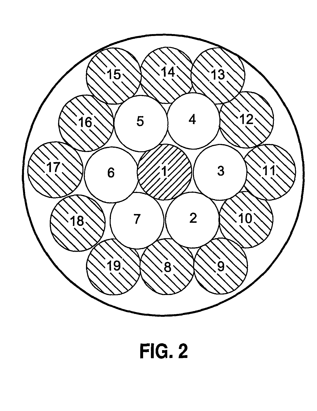
[0027]In the example illustrated in FIG. 1, antenna feed elements of the antenna system 100 are combined in three element sets. The first element set may include a center element 102, the second element set may include 6 inner ring elements 104, and the third element set may include 12 outer ring elements 106. FIG. 2 illustrates a cluster of antenna feed elements, in which element 1 is the center feed element, eleme...


PUM


Abstract

An antenna system has multiple antenna feed elements combined in a number of element sets independently controlled to provide a beam of a variable size. Multiple input power dividers are provided for dividing an input signal, and multiple phase controllers are respectively connected to outputs of the power dividers for producing a plurality of phase-shifted signals having prescribed phases. The phase-shifted signals are supplied to respective inputs of a hybrid matrix. Predetermined outputs of the hybrid matrix are connected to summation circuitry for providing in-phase power summation of signals produced at these outputs. The antenna elements in at least one of the element sets are controlled by a sum signal produced by the summation circuitry. The other element sets may be controlled by respective output signals of the hybrid matrix.

Description

FIELD OF THE INVENTION[0001]The present invention relates to antennas, and particularly to an antenna system capable of providing a beamwidth variable over a wide size range.BACKGROUND[0002]In antenna systems, such as satellite antenna systems used, for example, in a global positioning system (GPS) or in a communications system, a size of a produced beam is selected to cover a particular country or a geographic area. A beam size can be varied to increase or reduce a covered area.[0003]For example, U.S. Pat. No. 6,243,051 discloses a dual helical antenna for a GPS including a reflector and a focal point. Two multi-turn axial mode helical antenna elements are arranged on a support shaft extending axially from the reflector to the focal point. One of the helical antenna elements is disposed at the focal point, and the other antenna element is disposed at a defocused position to broaden the beam and covered area.[0004]However, this antenna system is constrained to large and small beams ...

Claims


Application Information

Patent Timeline
Patent Type & Authority Patents(United States)
IPC IPC(8): H04B7/185G01S3/16H01Q3/00H04M1/00
CPCH01Q25/002
Inventor MILBOURNE, THOMAS H.
Owner LOCKHEED MARTIN CORP
Why Eureka
Try Eureka