Mobile station position locating system

Inactive Publication Date: 2009-11-26
BROTHER KOGYO KK
View PDF13 Cites 21 Cited by
  • Summary
  • Abstract
  • Description
  • Claims
  • Application Information

AI Technical Summary

Benefits of technology

[0032]In particular, the difference in the received power represented in logarithm between one and the other of the base stations constituting the base station pair is not affected by a change in the transmitted radio wave power from the mobile station. Accor

Problems solved by technology

Accordingly, in calculation of the distance between the mobile station and the base station using the received power based on the previously obtained relation, an error may occur in the calculated distance.
This results in a problem that position

Method used


Image

  • Mobile station position locating system
  • Mobile station position locating system
  • Mobile station position locating system

Examples


first embodiment

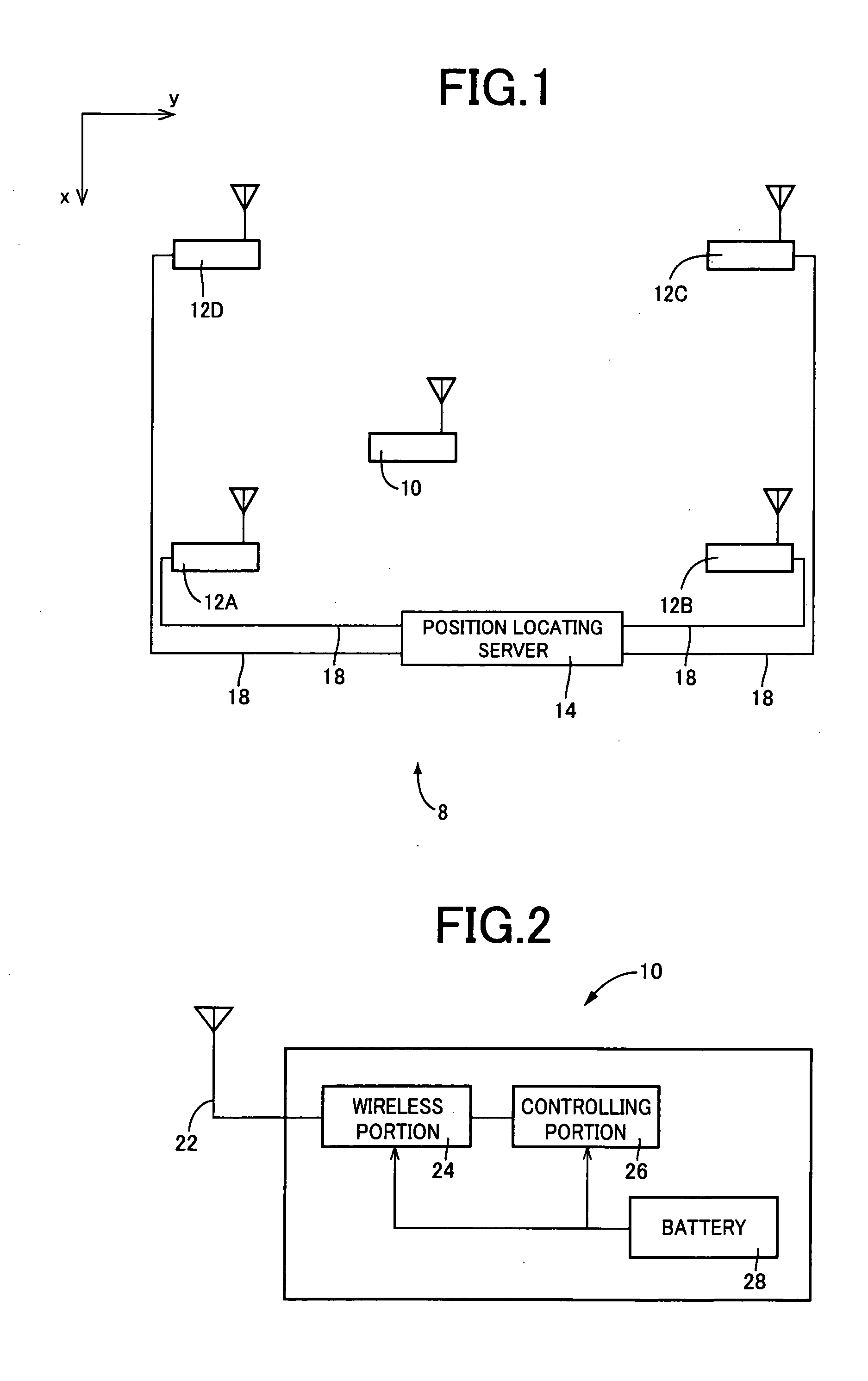
[0045]FIG. 1 shows one example of the structure of the mobile station position locating system 8 of the present invention. As shown in FIG. 1, the mobile station position locating system 8 comprises a mobile station 10, four base stations 12, and a position locating server 14. The four base stations 12 include a first base station 12A to a fourth base station 12D, each fixed to a known position, having a function to wirelessly communicate with the mobile station 10 (hereinafter, when the first base station 12A to the fourth base station 12D are not distinguished, they are referred to as base stations 12). The position locating server 14 comprises a so-called computer provided with CPU, RAM, ROM, input / output interfaces, etc., for example. The number of mobile stations 10 is not limited insofar as it is one or more. The base stations 12 are each connected to the position locating server 14 via a telecommunication cable 18, such as a LAN cable to be mutually intercommunicated.

[0046]In...

second embodiment

[0111]Hereinafter, a second embodiment of the present invention will be explained. In the following explanation, explanation of the portions common to the first embodiment is omitted with adding the same numerals thereof.

[0112]In the second embodiment, the principal part of the function of the mobile station 10 is expressed by the block diagram shown in FIG. 2, as in the first embodiment. Among the components, the wireless portion 24 has the same function as in the first embodiment. The controlling portion 26 has the following functions, in addition to the function of controlling the operation of the mobile station 10 in the first embodiment. Specifically, the controlling portion 26 has a function of adding an error detecting code added for detecting errors in a parity check bit and the like, to the data included in the radio wave transmitted from the mobile station 10 to each base station 12. The error detecting code is calculated from the transmitted data according to the predeter...


PUM


Abstract

A radio wave transmitted from a mobile station 10 is received in each base station 12, and, based on the received power measured by a received power measuring portion 38 of the base station, a distance ratio calculating portion 54 of a position locating server 14 calculates the difference in the received power between the paired base stations. Based on the difference in the received power, the distance ratio is calculated between the distance from one base station to the mobile station and the distance from the other base station to the mobile station. A locus creating portion 56 of the position locating server 14 creates a locus which is a sequence of points showing positions where the calculated distance ratio is realized. The position calculating portion 58 calculates an intersection of the loci for a plurality of base station pairs, thereby calculating a candidate for the mobile station.

Description

[0001]This application is based on Japanese Patent Application No. 2008-132551 filed on May 20, 2008, and content thereof is incorporated by reference.FIELD OF THE INVENTION[0002]The present invention relates to a mobile station position locating system in which a plurality of base stations receive a radio wave transmitted from a mobile station and which estimates a position of the mobile station based on the reception result, i.e., the received power. Especially, the present invention relates to a technology enabling an accurate position locating even when a change occurs in a transmitted power from the mobile station due to battery exhaustion, etc.DESCRIPTION OF THE RELATED ART[0003]A method has been suggested, in which a radio wave transmitted (sent) from a mobile station is received by a plurality of base stations, and the position of the mobile station is estimated based on the received power at each of the plurality of base stations. In this method, for example, received power...

Claims


Application Information

Patent Timeline
IPC IPC(8): H04W4/02G01S5/02H04W64/00
CPCG01S5/0294H04W64/00G01S5/14
Inventor YANO, YOSHIKINAGAI, TAKUYA
Owner BROTHER KOGYO KK
Why Eureka
Try Eureka