Calculating power loss for inductive power transmission

a power transmission and power loss technology, applied in the field of power transmission technology, can solve the problems of inability to calculate power loss in the field of inductive power transmission, metal objects positioned at the surface of the power transmitter, and affecting the operation of the power transmission system,

Active Publication Date: 2014-01-02
KONINKLIJKE PHILIPS ELECTRONICS NV
View PDF2 Cites 19 Cited by
  • Summary
  • Abstract
  • Description
  • Claims
  • Application Information

AI Technical Summary

Benefits of technology

[0009]It is an object of this invention to provide a method and devices for power transmission that allow the transmitter to avoid heating metal objects.
[0018]The measures have the effect that power loss is accurately determined because the received power and the transmitted power are determined according to the same time information, e.g. in a same, aligned, time window. The power loss in a metal object can be estimated by taking the difference between the net transmitted power and the gross received power. To prevent that too much power is dissipated into a metal object, the power transmitter terminates power transfer if the power loss exceeds a threshold. Advantageously metal objects are prevented to heat up by determining the power loss that is not part of the normal power loss of the system.
[0039]a unit for applying multiple instances of received power information communicated by the power receiver to increase the robustness of the power loss calculation method;

Problems solved by technology

A problem is that metal objects, positioned at the surface of the power transmitter, can reach an undesired high temperature (higher than 65° C.) due to eddy currents caused by the magnetic field generated by the power transmitter.
This is an unwanted situation.
Skin burning and plastic melting could result from this heating.

Method used


Image

  • Calculating power loss for inductive power transmission
  • Calculating power loss for inductive power transmission
  • Calculating power loss for inductive power transmission

Examples


Embodiment Construction

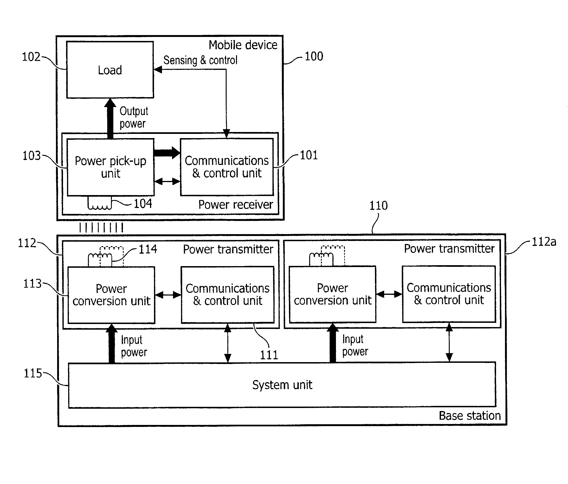
[0050]A method to prevent a metal object to heat up is to determine the power loss that is not part of the normal power loss of the system. The power loss in a metal object can be estimated by taking the difference between the net transmitted power and the gross received power. To prevent that too much power is dissipated into a metal object, the power transmitter terminates power transfer if the power loss exceeds a threshold.

[0051]To determine the power loss the power receiver estimates its gross received power e.g. by measuring its rectified voltage and current, multiplying current and voltage, and adding an estimation of the internal power losses in the power receiver. The power receiver communicates the received power to the power transmitter, e.g. with a minimum rate such as every 5 seconds. Such minimum rate means that the distance in time between the ends of two succeeding received power information data is maximally 5 seconds.

[0052]The power transmitter estimates its net tr...


PUM

PropertyMeasurementUnit
temperatureaaaaaaaaaa
power lossaaaaaaaaaa
received power parameteraaaaaaaaaa

Abstract

The invention proposes a method of calculating power loss in an inductive power transfer system comprising a power transmitter (112) for transmitting power inductively to a power receiver (110) via transmitter coil (114) and receiver coil (104), the method comprising a step of obtaining, by power transmitter, time information for time alignment to enable the power transmitter to align the time of calculating the power loss with the power receiver; and a step of calculating power loss during power transfer according to the obtained time information and received power parameter communicated from the power receiver.

Description

FIELD OF THE INVENTION[0001]The invention relates to a method of calculating power loss in an inductive power transfer system in a power transmitter.[0002]The invention further relates to method of enabling calculating power loss in an inductive power transfer system in a power receiver.[0003]The invention further relates to a power transmitter, a power receiver and a communication signal.[0004]The invention relates to the field of power transmission technology, particularly to method and device for calculating power loss during power transfer.[0005]Power transfer via magnetic induction is a well known method, mostly applied in transformers, having a tight coupling between primary and secondary coil. By separating primary and secondary coil in two devices, wireless power transfer between these devices becomes possible based on the principle of a loosely coupled transformer. The basic elements for such a system are a power transmitter, containing a primary coil and a power receiver, ...

Claims


Application Information

Patent Timeline
Patent Type & Authority Applications(United States)
IPC IPC(8): G01R21/00H01F38/14
CPCG01R21/00H01F38/14H04B5/0037H02J50/10H02J50/80H02J50/60G01R21/133
Inventor VAN WAGENINGEN, ANDRIES
Owner KONINKLIJKE PHILIPS ELECTRONICS NV
Why Eureka
Try Eureka