Self-ballasted lamp

a self-balancing and lamp technology, applied in the direction of electric lighting with batteries, gas-filled discharge tubes, electric circuit arrangements, etc., can solve the problems of poor radiation efficiency of led, reduced light emission of led, and shortened life of led, so as to achieve more efficient radiation

Inactive Publication Date: 2010-02-04
TOSHIBA LIGHTING & TECH CORP
View PDF15 Cites 75 Cited by
  • Summary
  • Abstract
  • Description
  • Claims
  • Application Information

AI Technical Summary

Benefits of technology

[0017]Then, providing the air-cooling unit inside the other edge side of the radiator to ventilate inside the radiator enables to improve radiation efficiency of the radiator and to suppress a rise in temperature of the light emitting element.
[0031]Then, providing the drive circuit on the one edge side of the substrate enables the other edge side of the substrate to be flat and closely contact with the radiator and thus more efficient radiation is enabled.

Problems solved by technology

In such a self-ballasted lamp, temperature of the LED is increased by the heat generated by the LED and such an increase in temperature causes a decrease in light emission of the LED, as well as shortened life of the LED.
However, in the case of a self-ballasted lamp having a globe, radiation efficiency of the LED is poor because the LED is covered with the globe and even if a metallic radiator is used, rise in temperature of the LED cannot be sufficiently suppressed.
Moreover, even if a heat-radiating fin is provided to the radiator of a self-ballasted lamp having a globe and a fan is provided inside the radiator like the case of an LED lamp without a globe so that heat transmitted to the radiator can be forcibly radiated, since the LED is covered with the globe, it is not possible to sufficiently suppress a rise in temperature of the LED.

Method used


Image

  • Self-ballasted lamp
  • Self-ballasted lamp
  • Self-ballasted lamp

Examples


seventh embodiment

[0167]Then, having the configuration similar to that of the seventh embodiment such as the one edge side of the radiator 13 is brought into close contact with the other main surface 21b of the substrate main body 21 having the LEDs 22 on the one main surface 21a and the air-cooling unit 15 is stored in the storage part 81 inside the radiator 13 while the drive circuit 85 for driving the air-cooling unit 15 is provided to the substrate main body 21 enables to obtain an effect similar to that of the above-mentioned embodiment.

[0168]Next, a further embodiment is shown in FIG. 15. FIG. 15 is a longitudinal-sectional view of a self-ballasted lamp. Here, the same reference numerals are given to the components having the same configuration and actions as those in each of the above-mentioned embodiments and description thereof is omitted.

[0169]In the further embodiment, the axis receiving part 105 of the air-cooling unit 15 in the above-mentioned embodiment is inserted into the attachment h...

ninth embodiment

[0174]In the embodiment, the LEDs 22 in the above-mentioned ninth embodiment are provided along one same circumference at a position in the vicinity of the outer circumference of the substrate main body 21 and the drive circuit 85 is provided on the center side of the substrate main body 21 except for the aperture 121, that is, at a position inside the LEDs 22.

[0175]The LEDs 22 are provided at a position overlapping at least a part outward of the radiator 13 when seen planarly, preferably at a position that is at a more inner side than the outer circumference of the radiator 13 and corresponds to the upper side of the heat-radiating fins 32 when seen planarly. In other words, the LEDs 22 are provided at a position that is outward more than the storage part 81 when seen planarly, that is, at a position outside the fan parts 108 of the fan 94 of the air-cooling unit 15.

[0176]Then, having the configuration similar to that of each of the above-mentioned embodiments such that the one edg...


PUM


Abstract

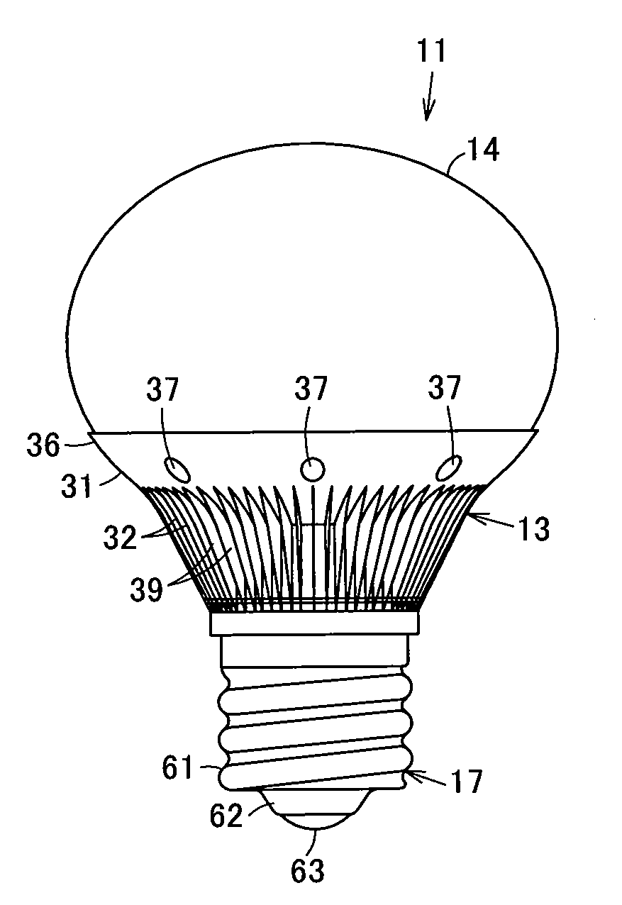
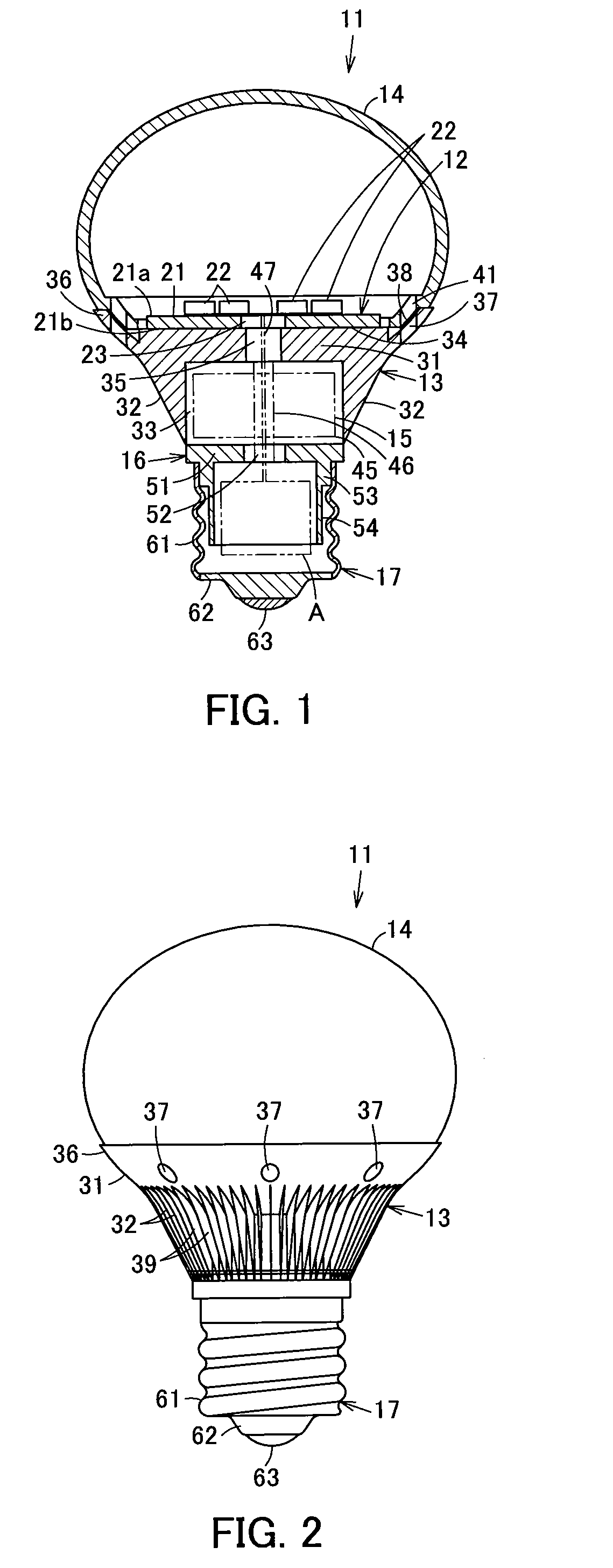
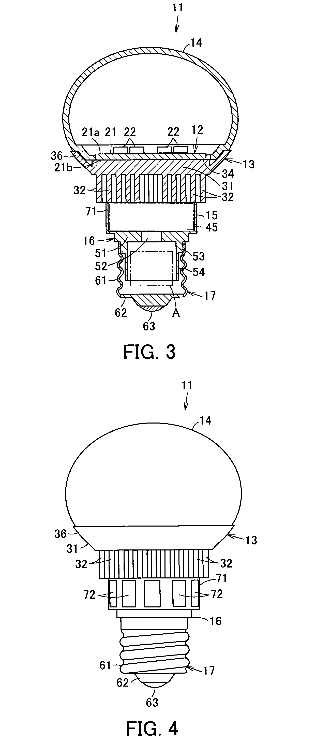
A substrate is attached to one edge side of a radiator and a globe is attached covering the substrate. Heat-radiating fins are provided on the other edge side of the radiator and an air-cooling unit is rotatably provided inside the heat-radiating fins which enables to freely rotate. A case storing a circuit part is attached to the other edge side of the radiator and a cap is provided to the case. By the wind blast from the air-cooling unit, the heat-radiating fins are caused to be a part of the ventilation path to allow for ventilation of the inside of the radiator.

Description

INCORPORATION BY REFERENCE[0001]The present invention claims priority under 35 U.S.C. §119 to Japanese Patent Application Nos. 2008-199035, 2008-252562, 2008-252567, 2008-252742 and 2008-280062 filed on Jul. 31, 2008, Sep. 30, 2008, Sep. 30, 2008, Sep. 30, 2008 and Oct. 30, 2008, respectively. The contents of these applications are incorporated herein by reference in their entirety.FIELD OF THE INVENTION[0002]The present invention relates to a self-ballasted lamp which can substitute for a general light bulb.BACKGROUND OF THE INVENTION[0003]Conventionally, a substrate mounting an LED is attached to an edge of a radiator, a globe is attached to the edge of the radiator in a manner that the globe covers the substrate, a case for storing a lighting circuit for lighting the LED is attached to the other edge of the radiator, and a cap is provided to the other edge of the case in a self-ballasted lamp using an LED as a light emitting element.[0004]In such a self-ballasted lamp, temperatur...

Claims


Application Information

Patent Timeline
Patent Type & Authority Applications(United States)
IPC IPC(8): H01K1/58
CPCF21K9/135F21V3/00F21Y2101/02F21V29/83F21V23/0492F21V29/773F21V29/02F21K9/232F21V29/67F21Y2115/10
Inventor BETSUDA, NOBUHIKOSUWA, TAKUMIKAWANO, HITOSHISAITO, AKIKOBESSHO, MAKOTOSHIBAHARA, YUSUKETAMAI, HIROKISHIBANO, NOBUOSHIMIZU, KEIICHI
Owner TOSHIBA LIGHTING & TECH CORP
Why Eureka
Try Eureka