Method for Producing an Optical Article Coated with an Antireflection or a Reflective Coating Having Improved Adhesion and Abrasion Resistance Properties

Inactive Publication Date: 2008-08-28
ESSILOR INT CIE GEN DOPTIQUE
View PDF4 Cites 75 Cited by
  • Summary
  • Abstract
  • Description
  • Claims
  • Application Information

AI Technical Summary

Benefits of technology

[0022]The present invention has especially been conceived to counteract the difficulty of the antireflection stack to adhere to the s

Problems solved by technology

However, it has been observed that inserting this sub-layer, while increasing the abrasion resis

Method used


Image

  • Method for Producing an Optical Article Coated with an Antireflection or a Reflective Coating Having Improved Adhesion and Abrasion Resistance Properties
  • Method for Producing an Optical Article Coated with an Antireflection or a Reflective Coating Having Improved Adhesion and Abrasion Resistance Properties
  • Method for Producing an Optical Article Coated with an Antireflection or a Reflective Coating Having Improved Adhesion and Abrasion Resistance Properties

Examples


Example

Examples 1 to 5

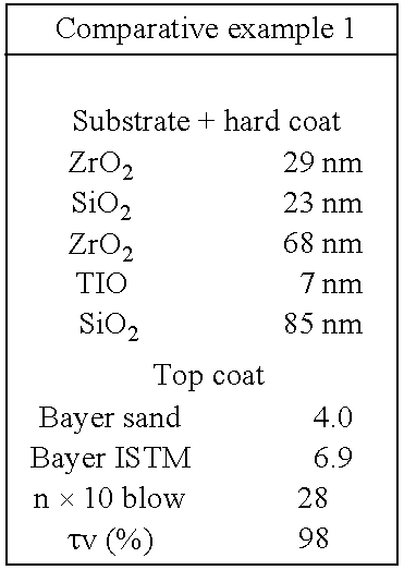
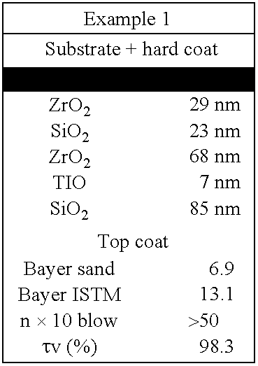
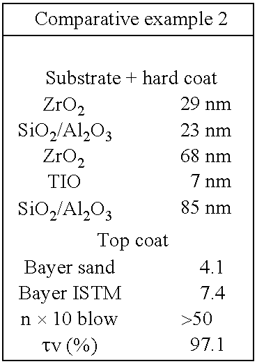
[0145]The method for producing optical articles does consists in introducing the substrate provided with an abrasion-resistant coating into a vacuum deposition chamber, in conducting a pumping step until a high vacuum was created, followed by a substrate surface activation step using an argon ion beam (IPC) under a pressure of 2.10−4 mBar, in stopping the ionic irradiation, in successively evaporating the required number of antireflection coating layers, in depositing the anti-smudge coating (top coat) and lastly in ventilating.

[0146]Forming the antireflection coating does comprise a deposition step for the SiO2 sub-layer at a rate of 1 nm / s, optionally under an O2 atmosphere at a pressure of 1.10−4 mBar (where indicated), a surface activation step for the sub-layer using an argon ion beam at a pressure of 1.7.10−4 mBar (same treatment as IPC already conducted directly on the substrate), stopping the ionic irradiation, depositing the first HI layer (ZrO2) at a rate of...

Example

Comparative Examples C1 to C5

[0148]The procedures used in the comparative examples were similar. The articles for the comparative examples 1 and 2 (examples C1 and C2) did not comprise any sub-layer. The sub-layer of the articles for the comparative examples 3 to 5 (examples C3 to C5) had been deposited under oxygen atmosphere but did not undergo any ionic pre-cleaning step before depositing the multilayered stack.

3. Characterizations

[0149]a. Characterization of the Abrasion Resistance

[0150]The abrasion resistance was evaluated by determining BAYER values on substrates provided with an sub-layer (except for examples C1 and C2) and with a multilayered stack.

BAYER Sand Test

[0151]Determining such a BAYER value was conducted in accordance with the ASTM Standard F 735.81. The higher the BAYER test value the stronger the abrasion resistance is.

[0152]This test consists in simultaneously stirring a glass sample and a glass specimen with an alternating movement in a tank comprising an abrasi...

Example

[0161]The comparative example C3 relates to an article having an sub-layer that did not undergo any ionic bombardment before depositing the multilayered stack.

[0162]As regards the articles of comparative examples 4 and 5 that had an sub-layer, the obtained adhesion values in the “n×10 blow” test are limited.

[0163]Comparing the Bayer values obtained for the examples C3 and 2, C4 and 4 or C5 and 5 enables to observe the positive effect of the ionic bombardment on the surface of the sub-layer before depositing the multilayered stack from the abrasion resistance point of view.

[0164]Such treatment does typically increase the cohesion between the sub-layer and the multilayered stack of the invention.

[0165]The examples 2, 4 and 5 which had a silica sub-layer deposited under O2 pressure regulation and with an ionic bombardment of the surface of the sub-layer obtained excellent ISTM Bayer values and adhesion values obtained for the “n×10 blow” test.

[0166]Moreover, a comparison between the ex...


PUM

PropertyMeasurementUnit
Thicknessaaaaaaaaaa
Thicknessaaaaaaaaaa
Fractionaaaaaaaaaa

Abstract

The invention relates to a method for producing an optical article having antireflection or reflective properties and comprising a substrate having at least one main surface, comprising the step of depositing a sub-layer onto a substrate's main surface, the step of treating the sub-layer by ionic bombardment and the step of depositing onto said sub-layer a multilayered stack comprising at least one high refractive index layer and at least one low refractive index layer. According to a preferred embodiment, the deposition of the sub-layer is conducted in a vacuum chamber in which a gas is supplied during the deposition step.

Description

BACKGROUND OF THE INVENTION[0001]The present invention relates to a method for producing an optical article comprising a substrate provided with an antireflection coating or a reflective coating comprising a sub-layer, having in particular an increased abrasion-resistance and good adhesion properties to the substrate.[0002]1. Field of the Invention[0003]In the ophthalmic optics field, ophthalmic lenses are traditionally provided with various coatings so as to give these lenses a plurality of mechanical and / or optical properties. Successive coating layers are thus traditionally formed onto an ophthalmic lens, such as impact-resistant coating layers, abrasion-resistant coating layers, antireflection and / or reflective coating layers.[0004]As defined hereunder, an antireflection coating means a coating that has been deposited onto the surface of an optical article, which does improve the antireflective properties of the optical end product. It makes it possible to reduce the light refle...

Claims


Application Information

Patent Timeline
IPC IPC(8): B05D1/36
CPCC23C14/022C23C14/024C23C14/083G02B1/12C23C14/10G02B1/115C23C14/086
Inventor THOMAS, MICHELEROISIN, PHILIPPE
Owner ESSILOR INT CIE GEN DOPTIQUE
Why Eureka
Try Eureka