Light emitting device

a technology light source, which is applied in the field of light emitting device, can solve the problems of shortening the life of the light emitting device, and achieve the effects of preventing degradation, high brightness, and prolonging the li

Active Publication Date: 2006-07-13
NICHIA CORP
View PDF5 Cites 68 Cited by
  • Summary
  • Abstract
  • Description
  • Claims
  • Application Information

AI Technical Summary

Benefits of technology

[0019] The light emitting device of the present invention includes the mode scrambler, and thus it can relieve a portion of the excitation light, which has partially high relative intensity, into the light with broad relative intensity, while maintaining high brightness due to all the excitation light radiated to the wavelength converting member. Therefore, it is possible to prevent degradation due to heating of the wavelength converting member that is caused by especially strong light emission intensity. Thus a high-performance light emitting device with longer life can be achieved.
[0020] Also, if the mode scrambler changes the radiation pattern of the excitation light introduced to the light guide to a different radiation pattern and radiates the excitation light from the light guide, the above described effects can be more positively achieved.
[0021] Furthermore, if the mode scrambler is formed as a member with a concave region and / or a convex region facing a part or all of the outer circumference in part or all of the longitudinal direction of the light guide, and the mode scrambler will bend the light guide in multiple directions or can be integrated to the light guide so that the diameter of the center region is changed by increasing or decreasing the thickness of the circumference of the light guide, and therefore the mode scrambler can be very easily achieved, and a high-performance device can be provided at a very low cost.
[0022] If the mode scrambler doubles or more than doubles the full width at half maximum value for the FFP of the excitation light radiated from the light guide, or reduces the intensity peak value to 80% or less for the FFP of the excitation light radiated from the light guide, heating of the wavelength changing material can be better prevented, and a high-performance light emitting device with longer life can be achieved.
[0023] The wavelength converting member comprises fluorescent material and resin, and when the fluorescent material and resin are mixed in a weight ratio of 0.1˜10:1, heat degradation caused by light with extremely high light density can effectively be prevented if the fluorescent material contains material with excellent temperature properties, particularly at least one type of material selected from a group including LAG, BAM, BAM:Mn, YAG, CCA, SCA, SCESN, SESN, CESN, and CaAlSiN3:Eu.
[0024] Furthermore, if a lens is provided between the excitation light source and the light guide, and the excitation light radiated from the excitation light source is guided to the light guide, it is possible to effectively use the excitation light. Thus it is possible to enhance the brightness.

Problems solved by technology

However, the light density is generally high, so the resins and the fluorescent material or the like which make up the wavelength converting member will be heated and degraded by the high density excitation light, thus leading to a shorter life for the light emitting device.

Method used


Image

  • Light emitting device
  • Light emitting device
  • Light emitting device

Examples


embodiment 1

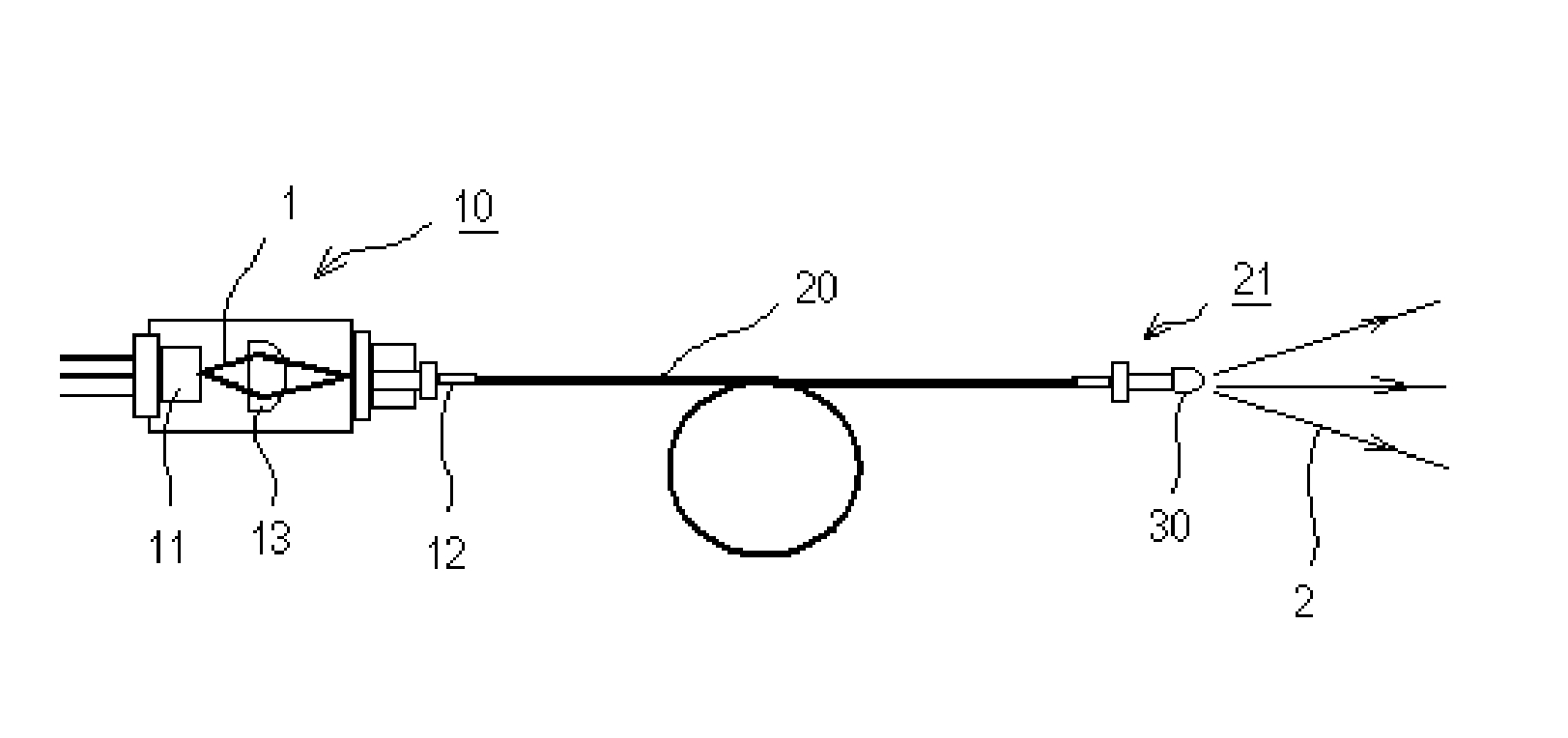
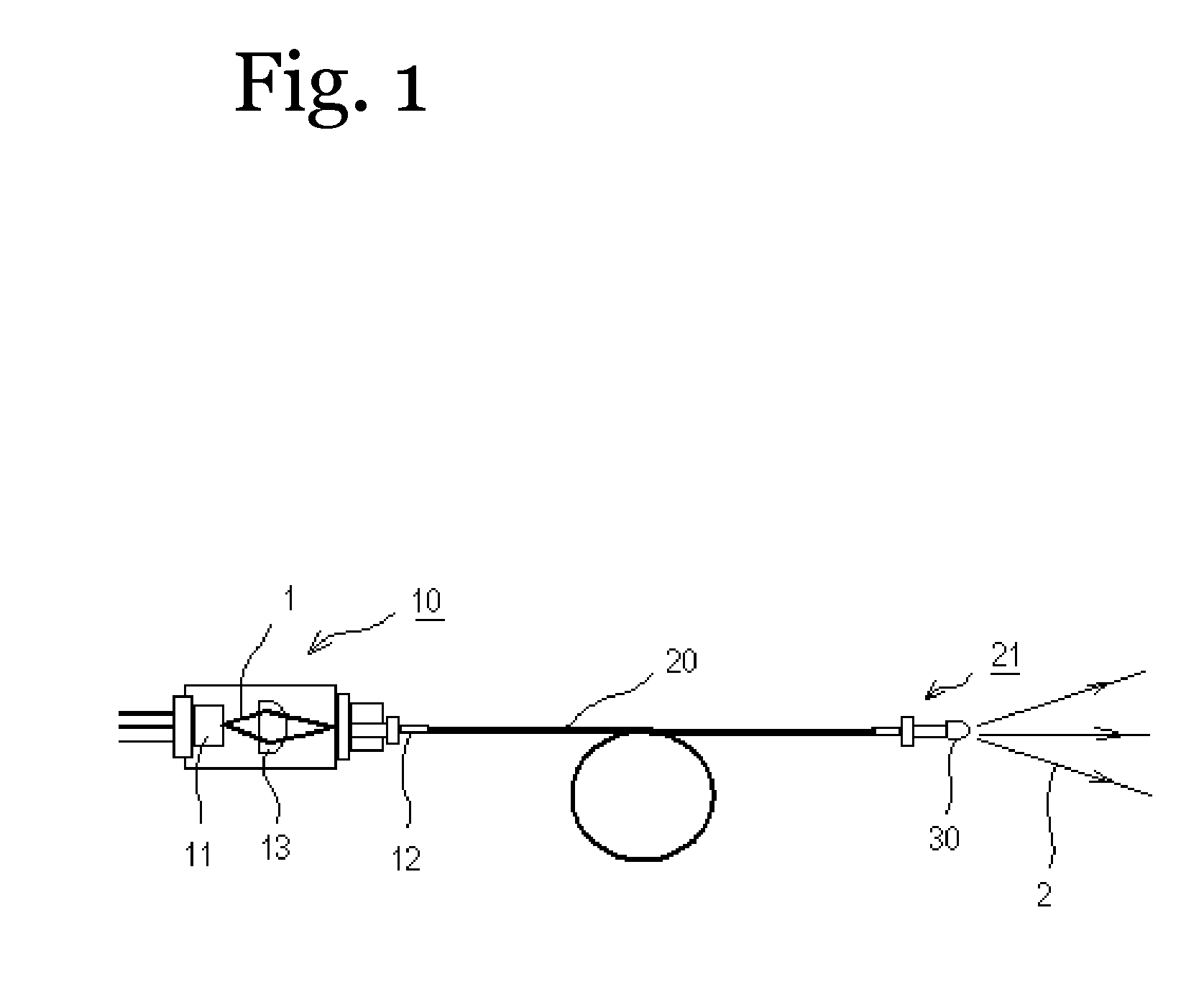
[0179] As shown in FIG. 1, the light emitting device of this embodiment comprises an excitation light source 10, a light guide 20, a mode scrambler (not shown in the figures) and a wavelength converting member 30.

[0180] The excitation light source 10 used a laser diode as a semiconductor light emitting element 11 which has an emission peak wavelength around 405 nm. The laser diode was a GaN type semiconductor element.

[0181] The light guide 20 was connected on one end to the light radiating part 12 of the excitation light source 10, and connected on the other end to the output unit 21. The light guide 20 was made from quartz and for instance was Si 114 (μm:core diameter) / 125 (μm:clad diameter).

[0182] As shown in FIG. 8, the mode scrambler 44 was a comb-like member which periodically mated to the light guide 20 in 4 predetermined locations to provide bends with a bending pitch P of 5 mm and a bending width W of 0.5 mm.

[0183] The wavelength converting member 30 was molded in order ...

embodiment 2

[0191] The light emitting device of this embodiment is essentially the same device as the device of the first embodiment except that 20 beads of approximately 4 mm in size were randomly positioned on the outer circumference of the light guide 20 as a mode scrambler 41 in order to bend the light guide 20 as shown in FIG. 3(b).

[0192] When evaluated similar to the first embodiment, the results showed that the radiation beam profile, luminous flux to light output, and device life were nearly similar.

embodiment 3

[0193] As shown in FIG. 4, this light emitting device was essentially the same device as the device of the first embodiment except that an SUS ferrule was welded as a mode scrambler 42 to create a force in six locations.

[0194] When evaluated similar to the first embodiment, the results showed that the radiation beam profile, luminous flux to light output, and device life were nearly similar.


PUM


Abstract

An object of the present invention is to provide a light emitting device which satisfies both properties of excellent color rendering properties for color reproduction and good light emitting efficacy, both of which are in the mutual trade-off relationship, by using a blue semiconductor laser which emits blue wavelength light with good light emitting efficiency and which has a linear spectrum in the blue wavelength band. A light emitting device is comprised of at least a first unit and at least a second unit. The first unit is comprised of a first excitation light source comprising a laser element emitting blue wavelength band excitation light, a wavelength converting member comprising at least one type of fluorescent material and which absorbs at least a portion of an excitation light emitted from the first excitation light source, converts the wavelength, and releases light with a wavelength longer than the first excitation light, and a light guide which has a refractive index in the center region of the cross-section which is higher than the refractive index of the surrounding region and which transmits the excitation light emitted from the first excitation light source. The second unit is comprised of a second excitation light source comprising a laser element which emits excitation light with a wavelength band shorter than the blue wavelength band excitation light emitted by the laser element, a wavelength converting member, and a light guide.

Description

TECHNICAL FIELD [0001] The present invention relates to a light emitting device, and more particularly relates to light emitting device which has an excitation light source, a wavelength converting member, and a light guide. BACKGROUND ART [0002] Conventionally, high-brightness light that can accurately reproduce color information has been demanded for devices such as endoscope devices and fiber scopes. [0003] Therefore, the use of semiconductor light emitting elements such as light emitting diode elements (LED) and laser diode elements (LD) or the like have been proposed as light sources to replace xenon lamps or the like (for instance, JP 2002-95634-A and JP 2003-515899-A). [0004] Semiconductor light emitting elements are compact, have good power efficiency, and emit brilliant colored light. Furthermore, there is no concern that the elements will burn out. In particular, semiconductor lasers emit light which has extremely high intensity compared to that of light emitting diodes, a...

Claims


Application Information

Patent Timeline
Patent Type & Authority Applications(United States)
IPC IPC(8): F21V9/00
CPCA61B1/0017A61B1/063A61B1/0638A61B1/0653A61B1/07G02B6/14G02B6/262G02B23/2469G02B2207/113H01S5/005H01S5/02284H01S5/4025H01S5/02251H01S5/0087H01S5/0085
Inventor HAMA, ATSUTOMONAGAHAMA, SHINICHIHAYASHI, YUKIHIRO
Owner NICHIA CORP
Why Eureka
Try Eureka