
Toner, and, developer, toner container, process cartridge, image forming apparatus and image forming method

a technology of toner container and developer, which is applied in the direction of electrographic process, electrographic process apparatus, instruments, etc., can solve the problems of high cost, ineffectiveness, and difficulty in uniform dispersing of additives such as colorants, and achieves excellent flowability, transferability, and anti-heat preservability. , the effect of preventing the blockage of the hea

Active Publication Date: 2006-09-14
RICOH KK
View PDF6 Cites 75 Cited by
  • Summary
  • Abstract
  • Description
  • Claims
  • Application Information

AI Technical Summary

Benefits of technology

The present invention provides a toner that has excellent low-temperature fixing ability, good offset resistance, and good reproducibility, even after a long period of use. The toner has a unique flow characteristic that allows for stable image formation on various transferring media without transfer errors or flowability issues. The toner is also excellent in resisting heat and pressure during fixing, and is not transferred back when adhered to a cleaning member. The invention also provides a developer, toner container, process cartridge, image forming apparatus, and image forming method using the toner.

Problems solved by technology

Specifically, a grinder, etc., are required to grind a toner composition, resulting in high cost, and thus the method is not effective.
Furthermore, it is difficult to disperse additives such as a colorant, and charge controlling agent into the binder uniformly.
The use of the toner in which the additives are not dispersed uniformly deteriorates flowability, developability, durability, image quality, etc.
However, toner particles obtained by suspension polymerization are generally spherical and have drawback of poor cleaning ability.
Poor cleaning ability causes non-transferred residual toner on a photoconductor, and the accumulation of such residual toner leads to background smear.
Moreover, residual toner contaminates components such as a charging roller, which charges a photoconductor by contact charging, and subsequently reduces the charging performance of the charging roller.
However, toner particles formed by emulsion polymerization have residual surfactants in large amounts inside the particles as well as on the surface thereof even after being washed by water.
As a result, charge stability of toner is reduced, the distribution of the amount of charge is increased, causing background smear on a printed image.
In addition, the residual surfactant contaminates photoconductor, charging roller, developing roller, etc.
Therefore, toner cannot fulfill its original function.
These proposals, however, cause increase of lowest fixing temperature, resulting in unsatisfactory fixing ability at low temperatures, i.e. energy-saving fixing ability.
In addition, this method, in which resin fine particles obtained by emulsion polymerization are associated to provide irregular-shaped toner particles, has another problem.
However, the releasing agent particles are captured inside the toner particles and therefore the improvement of the offset resistance is not sufficient.
In result, the surface properties of toner particles are different from one another, and it is impossible to form stable images for a long period.
Additionally, in a low-temperature fixing system, the resin fine particles that are concentrated at the surface of the toner particles inhibit fixing and therefore the range of fixing temperature is not sufficient.
Therefore, although the toner particle has a shell structure, the surface of the toner particle is a usual resin without any ingenious feature so that when the toner particle is targeted at fixing at a lower temperature, there is a problem that it is not satisfactory from the standpoint of anti-heat preservability and environmental charge stability.
Polyester resins are not generally used because they are difficult to be made into particles, it is uneasy to control particle diameter, diameter distribution, particle shape, etc., and their fixing ability is insufficient under the condition of fixing at a lower temperature.
The toner in these proposals, however, causes the reduction of melting temperature at the same time, resulting in the deterioration of offset resistance.
However, as the diameter of toner particles becomes smaller, the transferability and fixing ability tend to decrease, and image quality becomes poor.
Especially, with respect to fixing, fixing ability at a halftone portion becomes worse.
In order to increase speed more, the round toner is required to be fixed quickly; however, in a present situation, such round toner that has both quick fixing ability and fixing ability at low temperature has not been achieved.
Toner may be subjected to severe circumstances such as high temperature and humidity, and low temperature and humidity during storage and transport after the production.
However, in the present situation, effective means for such demand has not been found especially with respect to spherical toner.
A portion of toner image is transferred to the surface of fixing roller to adhere, and the transferred portion of toner image is re-transferred to the next receiving sheet, leading to the pollution of the receiving sheet.
Therefore, when the surface temperature of heating roller is high, the toner of the uppermost layer tends to cause offset phenomenon, and when the surface temperature of heating roller is low, toner does not fix to the receiving sheet because the toner of the lowermost layer does not melt sufficiently, causing low-temperature offset phenomenon easily.
However, shearing force on the toner becomes very large, receiving sheet winds around the fixing roller, i.e., so-called winding offset occurs, and a trace of separating pawls for separating the receiving sheet from the fixing roller is likely to appear on a fixed image.
Further, inferior fixed images are likely to occur, such as such as failure of line images during fixing and toner scattering, due to a high pressure.
However, the use of such a toner having a low melt viscosity in low speed fixation is likely to cause an offset phenomenon at high temperature.
Smaller particle size toner increases the resolution and clearness of an image, but impairs the fixability of a halftone image.
Thus, offset phenomenon is likely to be caused and fixed image is likely to have low quality.
In these proposals, the effect by defining the molecular mass distribution or the effect by olefin having low molecular mass improves fixing at low temperatures and anti-heat preservability; however, these binder resins do not meet the recent demand for energy-saving and low-power enough and further investigation has been desired.
However, in the present situation, it is difficult to develop such toner that satisfies all these properties in light of balance between hot offset property and preservability.
Although the dry toner proposed by JP-A No. 11-133665 is novel in that binder obtained as a result of a urethane reaction is employed, it is produced by a pulverization process and does not have satisfactory fixing ability at low temperatures.
However, in such granulation in water, a pigment in an oil phase aggregates at the interface with an aqueous phase, which leads to decreased volume resistivity or uneven pigment distribution and causes problems in fundamental properties of the toner.
However, each Patent Literature dose not describe adequately the effects of the combination of properties and / or processes or effects of the balance between detailed conditions, and thus effects on the problems may not be significantly achieved.

Method used

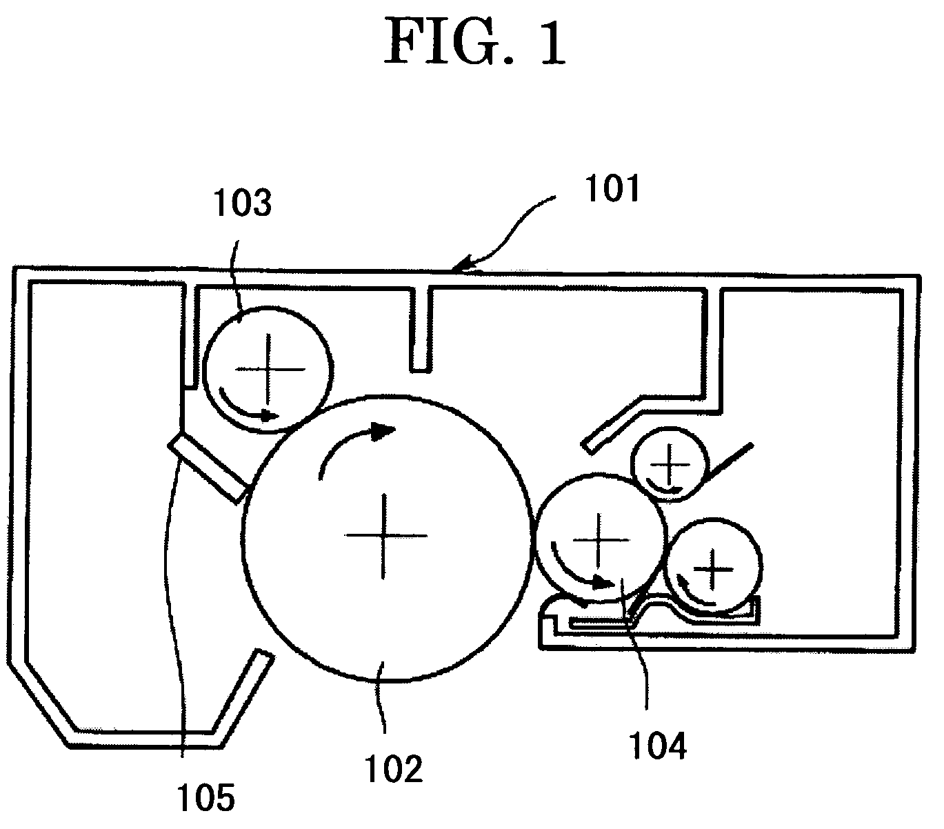
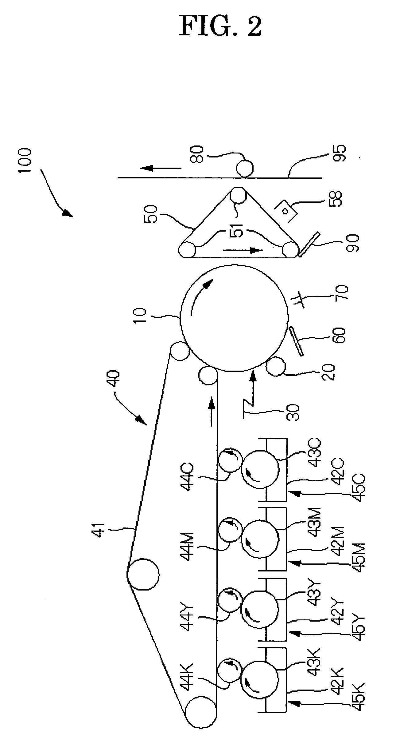
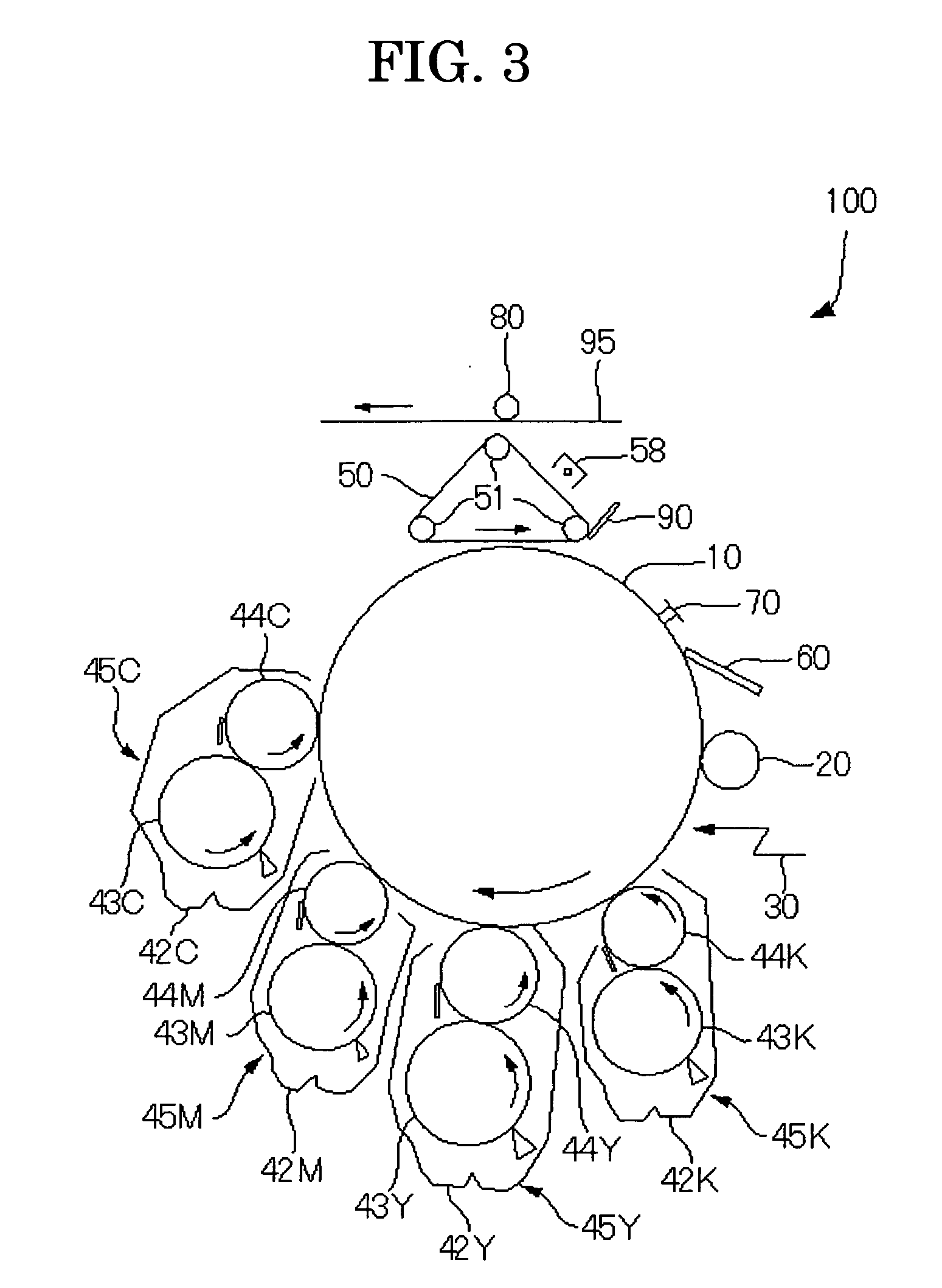

Image

  • Toner, and, developer, toner container, process cartridge, image forming apparatus and image forming method
  • Toner, and, developer, toner container, process cartridge, image forming apparatus and image forming method
  • Toner, and, developer, toner container, process cartridge, image forming apparatus and image forming method

Examples


example a-1

—Synthesis of Organic Partide Emulsion

[0527] To a reaction vessel provided with stirrer and thermometer, 683 parts of water, 11 parts of sodium salt of sulfuric acid ester of methacrylic acid ethylene oxide adduct (ELEMINOL RS-30 by Sanyo Chemical Industries, Ltd.), 83 parts of styrene, 83 parts of methacrylic acid, 110 parts of butyl acrylate and 1 part of ammonium persulphate were introduced, and stirred at 400 rpm for 15 minutes to give a white emulsion. This was heated, the temperature in the system was raised to 75° C. and the reaction was performed for 5 hours. Next, 30 parts of an aqueous solution of 1% ammonium persulphate was added, and the reaction mixture was matured at 75° C. for 5 hours to obtain an aqueous dispersion of a vinyl resin (copolymer of styrene-methacrylic acid-butyl acrylate-sodium salt of sulfuric acid ester of methacrylic acid ethylene oxide adduct). This is referred to as “particle dispersion 1”.

[0528] The volume average particle diameter of particles ...

example a-2

[0555]“toner 2” was produced in the same way as in Example A-1, except that, in Example A-1, “low molecular mass polyester 1” was changed to “low molecular mass polyester 2” having characteristics shown in Table 1.

[0556] For the obtained toner, characteristics of toner were measured in the same way as in ExampleA-1. Results are shown in Table 2.

example a-3

[0563]“toner 6” was produced in the same way as in Example A-1, except that, in Example A-1, “low molecular mass polyester 1” was changed to “low molecular mass polyester 4” having characteristics shown in Table 1.

[0564] For the obtained toner, characteristics of toner were measured in the same way as in Example A-1. Results are shown in Table 2.


PUM

PropertyMeasurementUnit
Tgaaaaaaaaaa
glass-transition temperatureaaaaaaaaaa
temperatureaaaaaaaaaa

Abstract

A toner which includes a toner material, wherein the toner satisfies the following formula: 0° C.≦ΔTm≦20° C. where ΔTm represents Tma (° C.)−Tmb (° C.), Tma (° C.) is ½ flown-out temperature of the toner by a capillary type flow tester, and Tmb (° C.) is ½ flown-out temperature of a melt kneaded mixture of the toner by the capillary type flow tester, and wherein Tma is from 130° C. to 200° C.

Description

CROSS-REFERENCE TO RELATED APPLICATIONS [0001] This is a continuation of Application PCT / JP20041013559, filed on Sep. 16, 2004 BACKGROUND OF THE INVENTION [0002] 1. Field of the Invention [0003] The present invention relates to toners for developing electrostatic images of electrophotography, electrostatic recording, electrostatic printing, and the like; and to developers, toner containers, process cartridges, image forming apparatuses, and image forming methods using the toners. [0004] 2. Description of the Related Art [0005] Image formation by e.g. electrophotographic method is generally carried out by a series of processes including: forming a latent electrostatic image on a photoconductor (latent electrostatic image bearing member); developing the latent electrostatic image by a developer containing a toner to form a visible image (toner image); then transferring the visible image to a recording medium such as paper; and fixing the image to form an fixed image. [0006] The toner ...

Claims


Application Information

Patent Timeline
Patent Type & Authority Applications(United States)
IPC IPC(8): G03G9/08G03GG03G5/08G03G9/087
CPCG03G9/0804G03G9/0819G03G9/0821G03G9/0827G03G9/08708G03G9/08711G03G9/08755G03G9/08797G03G9/10
Inventor NAKAYAMA, SHINYAMOCHIZUKI, SATOSHIIWAMOTO, YASUAKIASAHINA, YASUOKOTSUGAI, AKIHIROISHII, MASAYUKIUCHINOKURA, OSAMUNAKAJIMA, HISASHIICHIKAWA, TOMOYUKIUTSUMI, TOMOKOSAKATA, KOICHISUGIURA, HIDEKIEMOTO, SHIGERUAWAMURA, JUNICHITOMITA, MASAMIHONDA, TAKAHIROYAGI, SHINICHIROSUZUKI, TOMOMIYAMADA, HIROSHINANYA, TOSHIKIHIGUCHI, HIROTOSASAKI, FUMIHIROSHIMOTA, NAOHITO
Owner RICOH KK
Learn More