Spiral hair curling iron

a curling iron and spiral technology, applied in the field of spiral curling irons, can solve the problems of affecting the curling process, and affecting the curling effect, so as to reduce the tangling of the electrical cord

Inactive Publication Date: 2012-03-13
JACKSON MICHELE M
View PDF37 Cites 71 Cited by
  • Summary
  • Abstract
  • Description
  • Claims
  • Application Information

AI Technical Summary

Benefits of technology

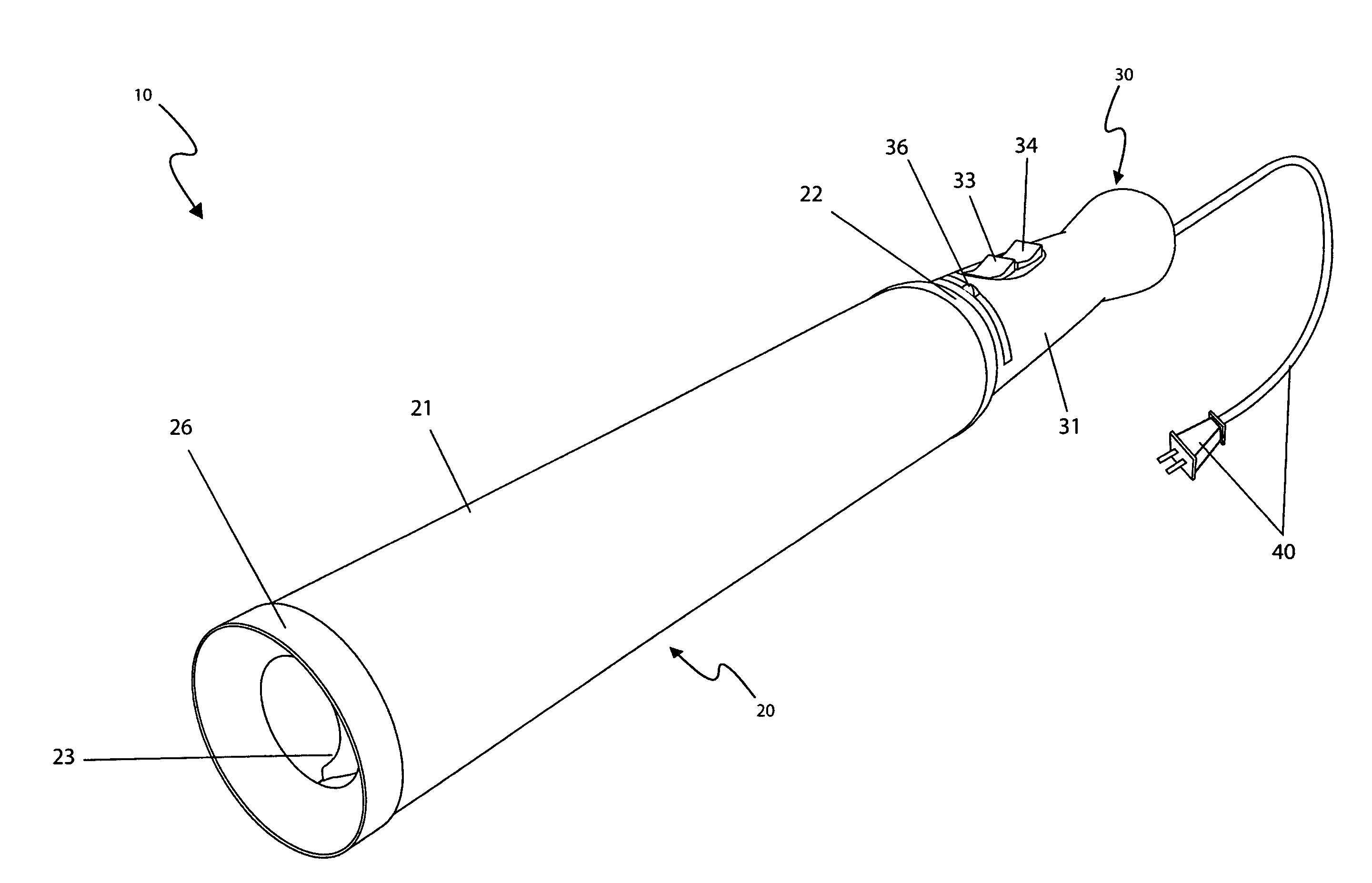
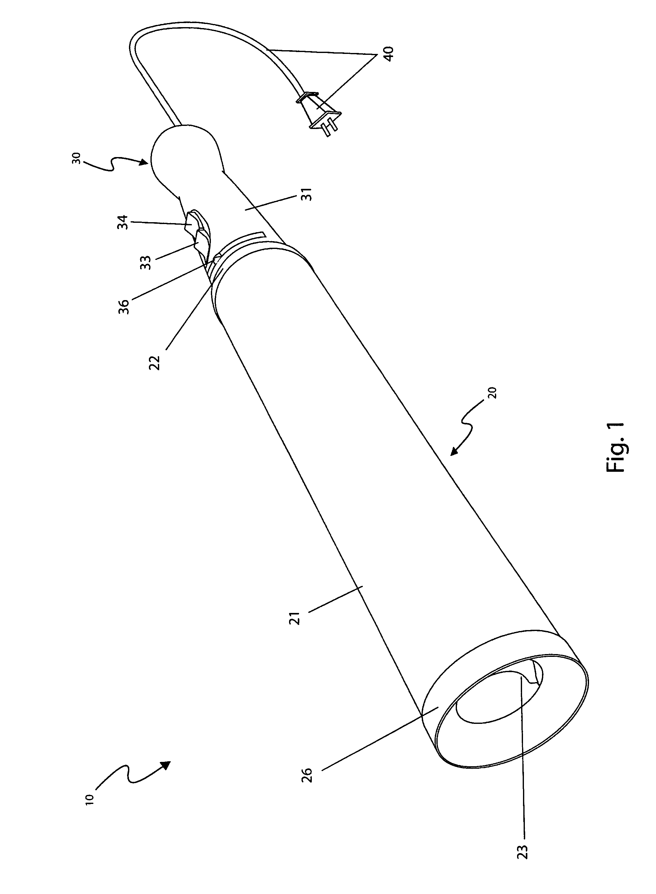
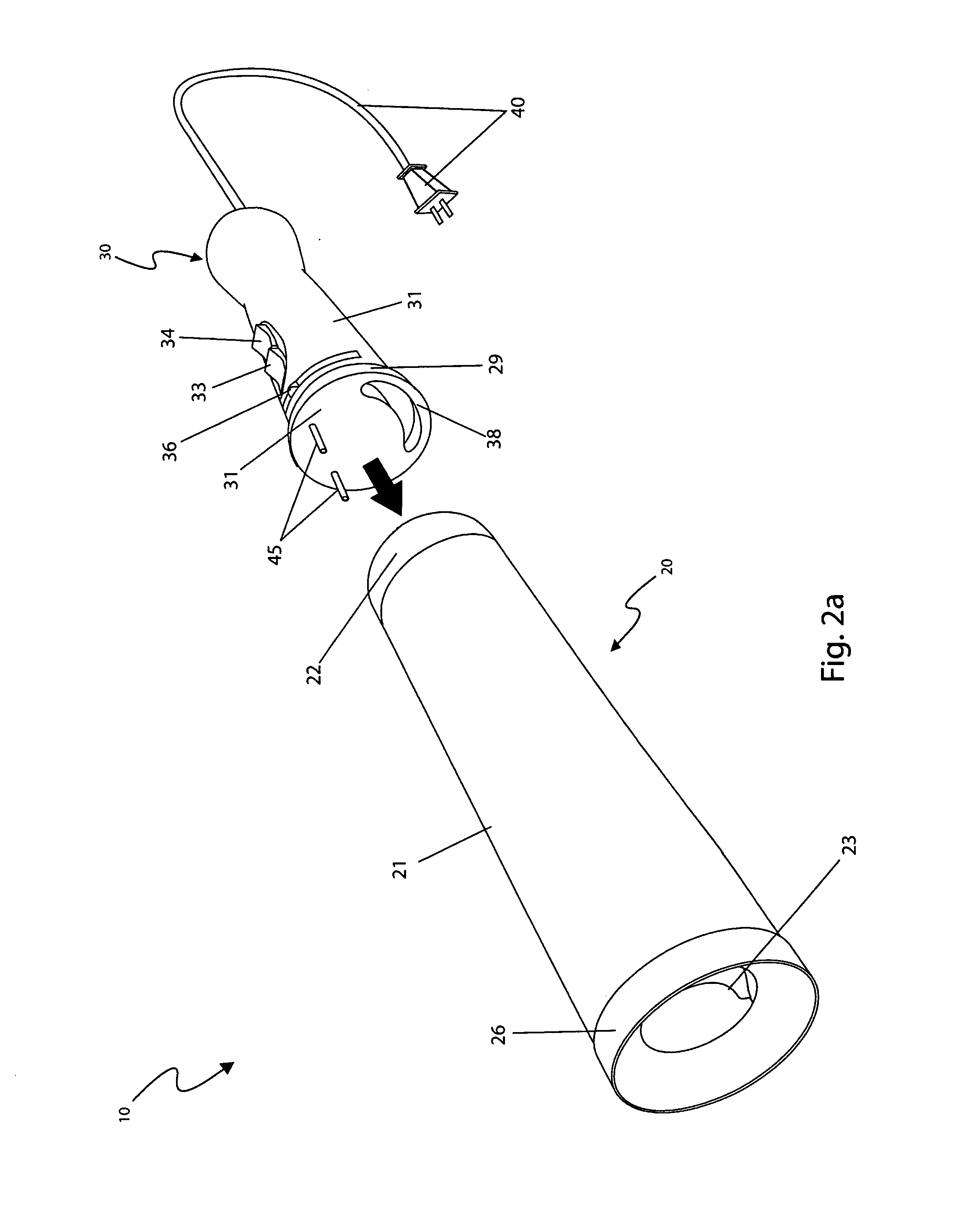
[0021]Still another object of the spiral hair curling iron provides a handle body comprising a comfortable cylindrical ergonomic design with a rounded end portion to aid in grasping and is made using heat insulating materials.
[0022]Another object of the spiral hair curling iron provides a flexible cord attachment that reduces tangling of the electrical cord during use.
[0023]A further object of the spiral hair curling iron may be used for exten

Problems solved by technology

Many times, users accidentally contact the hot heating tube and become burned on their arms and hands areas.
Even if one does not burn themselves, the process of curling one's hair takes a valuable amount of time.
To properly use conventional curling irons requires twisting and holding the apparatus for prolonged periods of time.
The contortions required can and frequently do result in the user being burned.
Unfortunately, this patent does not appear to disclose a hair curling iron that comprises a vacuum fan to move hair into an internal cylinder attachment with heating coils contained therein.
Unfortunately, this patent does not appear to disclose a spiral hair curling iron comprising a removable cylinder assembly with internal spiral heating elements and a handle assembly with a vacuum fan to move hair into the curling iron for curling.
Unfortunately, this patent does not appear to disclose a spiral hair curling iron that comprises a fan-driven means to move hair into a detachable cylinder assembly with an internal heating element to curl hair.
Unfortunately, this patent does not appear to disclose a s

Method used


Image

  • Spiral hair curling iron
  • Spiral hair curling iron
  • Spiral hair curling iron

Examples


Embodiment Construction

[0041]The best mode for carrying out the invention is presented in terms of its preferred embodiment, herein depicted within FIGS. 1 through 5. However, the invention is not limited to the described embodiment and a person skilled in the art will appreciate that many other embodiments of the invention are possible without deviating from the basic concept of the invention, and that any such work around will also fall under scope of this invention. It is envisioned that other styles and configurations of the present invention can be easily incorporated into the teachings of the present invention, and only one particular configuration shall be shown and described for purposes of clarity and disclosure and not by way of limitation of scope.

[0042]The terms “a” and “an” herein do not denote a limitation of quantity, but rather denote the presence of at least one of the referenced items.

[0043]The present invention describes a spiral hair curling iron (herein described as the “apparatus”) 1...


PUM


Abstract

A hair curling iron that forms spiral curls having an integral vacuum system and an internal heating tube is designed to eliminate the need for manual rotation of the entire curling iron when forming spiral hair curls. The curling iron provides a slot into which the hair is pulled by an integral vacuum fan mounted within the handle and controlled by an on/off pushbutton. When activated, the vacuum fan pulls the hair into the curling iron and around an interior heating tube. After several seconds, the pushbutton is released and a spiral curl is pulled out of the curling iron. A separate illuminating switch provides control of the heating portion of the curling iron. The danger of accidental burns is greatly reduced due to the interior location of the hot surfaces.

Description

RELATED APPLICATIONS[0001]The present invention was first described in and claims the benefit of U.S. Provisional Application No. 60 / 998,366 filed Oct. 11, 2007, the entire disclosures of which are incorporated herein by reference.FIELD OF THE INVENTION[0002]The present invention relates generally to a multiple tubular container device for mounting thereto a surface and capable of storing a plurality of elongated tubular containers slidingly placed therein corresponding receivers, further comprising a mounting means, a first fixture and a second fixture removably mounted thereto said device, and a handle.BACKGROUND OF THE INVENTION[0003]Hairstyles are as unique as one's personality. One (1) popular tool used by many to style their hair is that of the curling iron. It is commonly used to add style, body, flips, flair and the like to ones hair in a quick manner with a minimum of fuss. However, to do these tasks, one must grab a swath of hair in the curling iron and then turn the whole...

Claims


Application Information

Patent Timeline
IPC IPC(8): A45D7/02A45D2/36A45D1/04A45D4/12A45D20/12A45D20/00A45D4/06A45D1/02A45D2/22
CPCA45D1/04A45D7/02A45D1/28
Inventor JACKSON, MICHELE M.
Owner JACKSON MICHELE M
Why Eureka
Try Eureka