Spacecraft payload orientation steering

a technology for orientation steering and spacecraft, applied in vehicle position/course/altitude control, process and machine control, instruments, etc., can solve problems such as insufficient technique, multipath fading, and foliage attenuation, and achieve the effect of optimizing the steering angle of payload

Active Publication Date: 2010-07-15
MAXAR SPACE LLC
View PDF14 Cites 27 Cited by
  • Summary
  • Abstract
  • Description
  • Claims
  • Application Information

AI Technical Summary

Benefits of technology

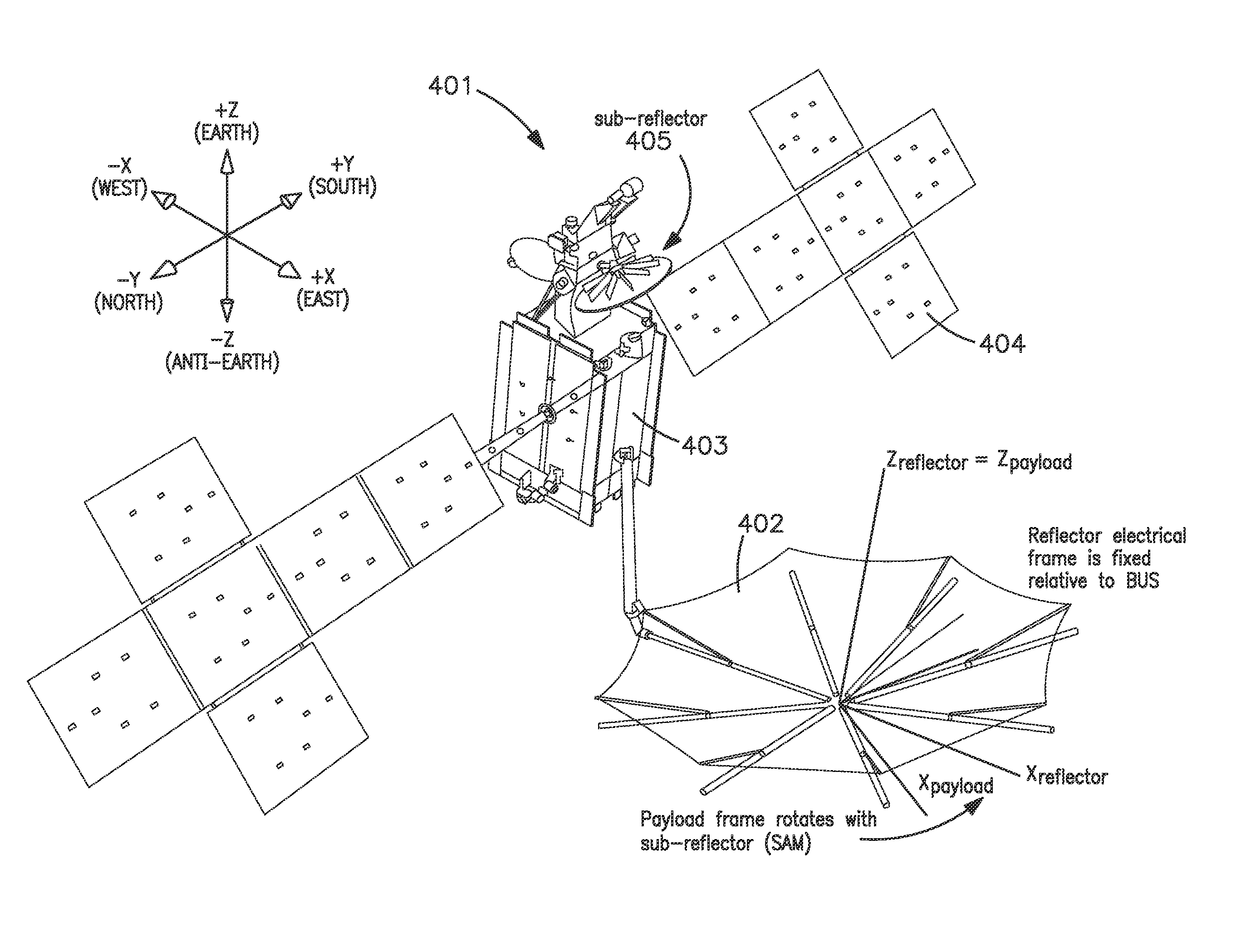
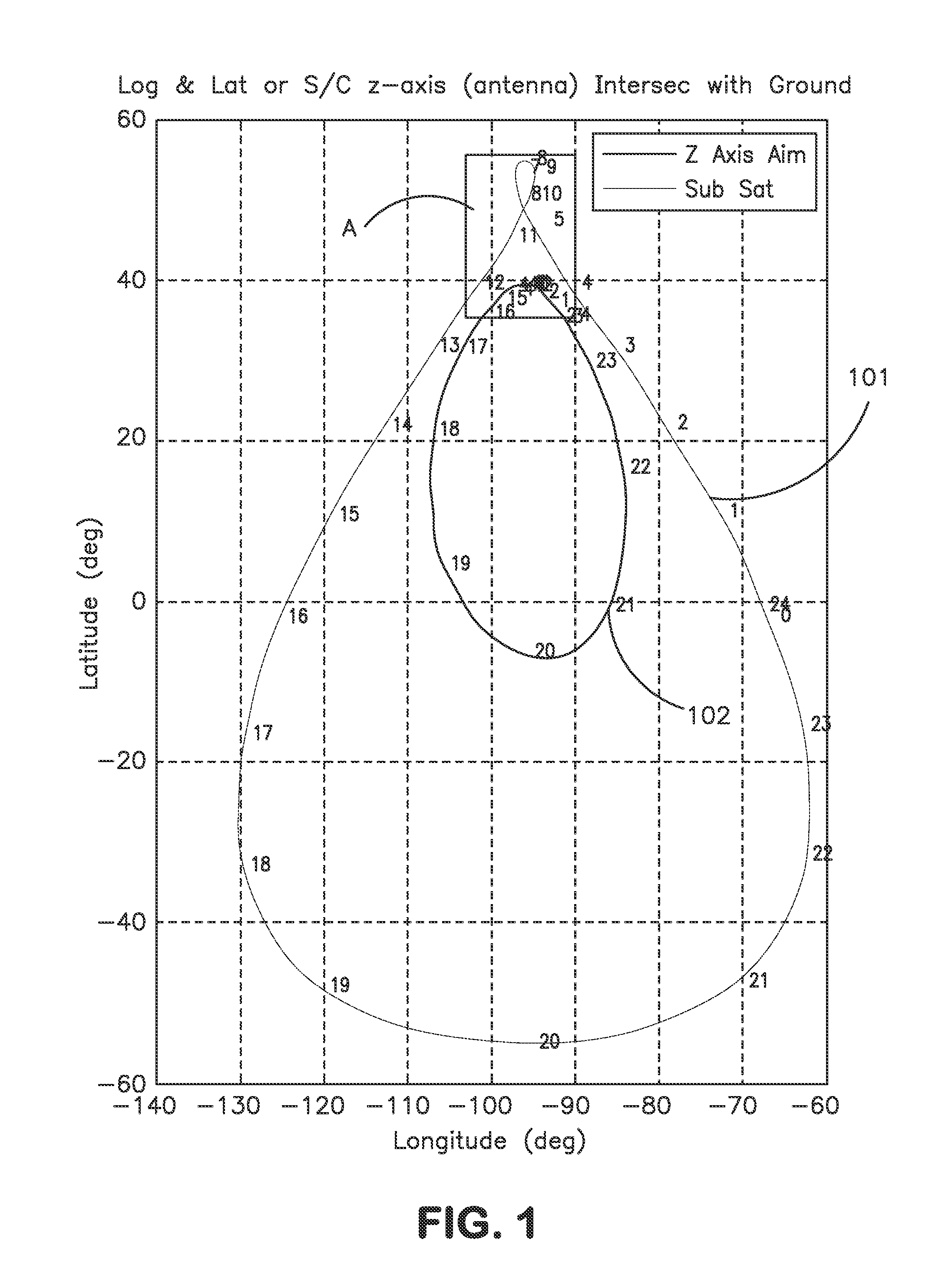
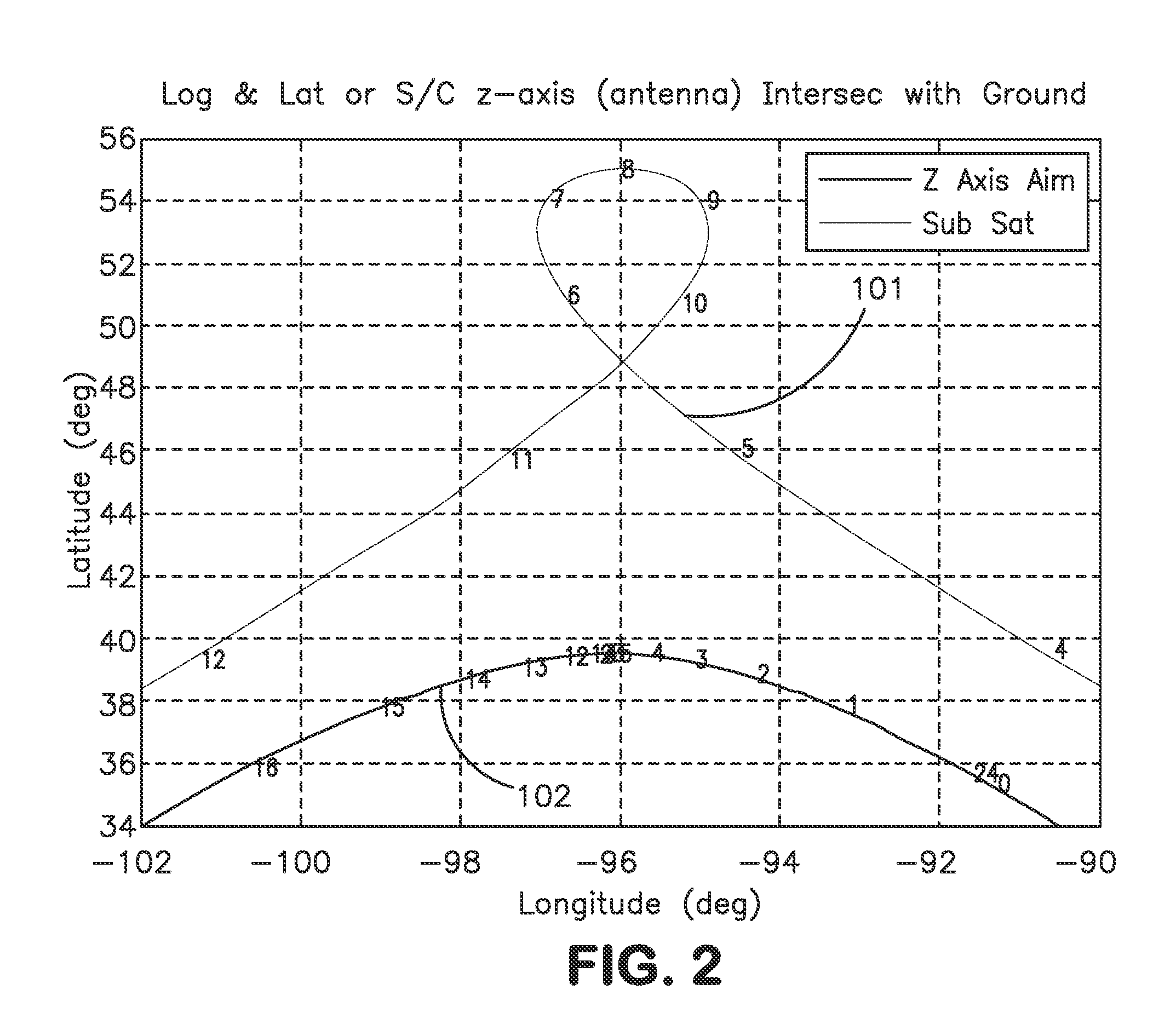
[0012]The present inventors have recognized that a payload orientation may be actively steered toward coordinates of an optimal payload target notwithstanding that these coordinates have a complex motion across the Earth's surface, and with respect to both the spacecraft and a spacecraft nadir. Advantageously, the desired payload orientation as a function of spacecraft location may be fitted with polynomial and Fourier series functions parameterized by outputs that may be obtained from an onboard orbit propagator processor. Such outputs, including the actual spacecraft longitude, latitude, radius and the argument of latitude, may be updated on a near-continuous basis by the onboard orbit propagator processor and take into account, for example, orbital drift. By linking an optimal EIRP-maximizing steering profiles to the onboard orbit propagator processor, the spacecraft may autonomously correct for orbital perturbations, notwithstanding substantial drift with respect to nominal orbital parameters such as inclination and eccentricity. Furthermore, optimized payload steering angles (

Problems solved by technology

At the latitudes of service areas containing many population centers of interest, for example in North America, Europe, and Asia, the elevation angle from the intended service area to the GSO spacecraft is small enough that service outages, for example from physical blockage, multipath fading, and foliage attenuation, are problematic.
To the extent that a geosynchr

Method used


Image

  • Spacecraft payload orientation steering
  • Spacecraft payload orientation steering
  • Spacecraft payload orientation steering

Examples


Embodiment Construction

[0026]Specific exemplary embodiments of the invention will now be described with reference to the accompanying drawings. This invention may, however, be embodied in many different forms, and should not be construed as limited to the embodiments set forth herein. Rather, these embodiments are provided so that this disclosure will be thorough and complete, and will fully convey the scope of the invention to those skilled in the art.

[0027]It will be understood that when an element is referred to as being “connected” or “coupled” to another element, it can be directly connected or coupled to the other element, or intervening elements may be present. Furthermore, “connected” or “coupled” as used herein may include wirelessly connected or coupled. It will be understood that although the terms “first” and “second” are used herein to describe various elements, these elements should not be limited by these terms. These terms are used only to distinguish one element from another element. Thus...


PUM


Abstract

Spacecraft payload orientation steering is provided for an orbiting spacecraft in motion along an orbit track around a celestial body, the orbit track having a nominal inclination with respect to an equatorial orbit, a substantial eccentricity, and a drift angle with respect to the nominal inclination. Coordinates of an optimal payload target location as a function of a spacecraft position along the orbit track are determined, the target location being on the surface of the celestial body and having a substantial motion with respect to the surface and with respect to a spacecraft nadir. A payload of the spacecraft is substantially aligned with the determined coordinates by steering the satellite body to correct for at least one of the inclination drift angle, and the eccentricity, thereby adjusting the spacecraft orientation as a function of the spacecraft position along the orbit track.

Description

RELATED APPLICATIONS[0001]The present patent application claims the priority benefit of commonly owned U.S. provisional patent application 61 / 144,526, filed Jan. 14, 2009, entitled “Spacecraft Payload Orientation Steering”, which is hereby incorporated by reference in its entirety into the present patent application.TECHNICAL FIELD[0002]This invention relates generally to spacecraft and, in particular, to methods and apparatus for orientation steering of a spacecraft such that optimal payload steering profiles are determined and achieved.BACKGROUND OF THE INVENTION[0003]The assignee of the present invention manufactures and deploys spacecraft for communications and broadcast services. Many such spacecraft operate in a geosynchronous orbit having a period equal to one sidereal day (approximately 23.93 hours).[0004]A particular type of geosynchronous orbit is a geostationary orbit (GSO), characterized as being substantially circular and co-planar with the Earth's equator. A satellite ...

Claims


Application Information

Patent Timeline
IPC IPC(8): B64G1/36G05D1/00
CPCB64G1/242B64G1/24B64G1/244
Inventor MUNIR, SAGHIRPRICE, XENMACHLIS, MATTHEW
Owner MAXAR SPACE LLC
Why Eureka
Try Eureka