
Tray for ink jet printer and method of manufacturing golf ball having mark

Inactive Publication Date: 2010-07-22
SUMITOMO RUBBER IND LTD
View PDF5 Cites 19 Cited by
  • Summary
  • Abstract
  • Description
  • Claims
  • Application Information

AI Technical Summary

Benefits of technology

[0020]According to the tray, for the ink jet printer, according to the present invention, displacement of the golf ball does not occur. The tray can contribute to improvement of marking accuracy of the ink jet printer. According to the tray, the holder can be inverted with the golf ball being fixed thereto. Thus, printing on both sides with excellent marking accuracy is possible. The tray can contribute to improvement of customer satisfaction.

Problems solved by technology

The golf ball is not fixed to the tray, and thus the golf ball moves due to vibrations or the like during printing.
This movement causes displacement of the golf ball.
The tray affects marking accuracy of the printer.
Because the tray cannot be inverted with a golf ball being fixed thereto, when marks are printed on both sides, it is not easy to form the marks on one side and the reverse side at positions symmetrical to each other.
The tray has a problem that it is difficult to print a mark at a position desired by a user.

Method used


Image

  • Tray for ink jet printer and method of manufacturing golf ball having mark
  • Tray for ink jet printer and method of manufacturing golf ball having mark
  • Tray for ink jet printer and method of manufacturing golf ball having mark

Examples


Embodiment Construction

[0039]The following will describe in detail the present invention based on preferred embodiments with reference to the accompanying drawings.

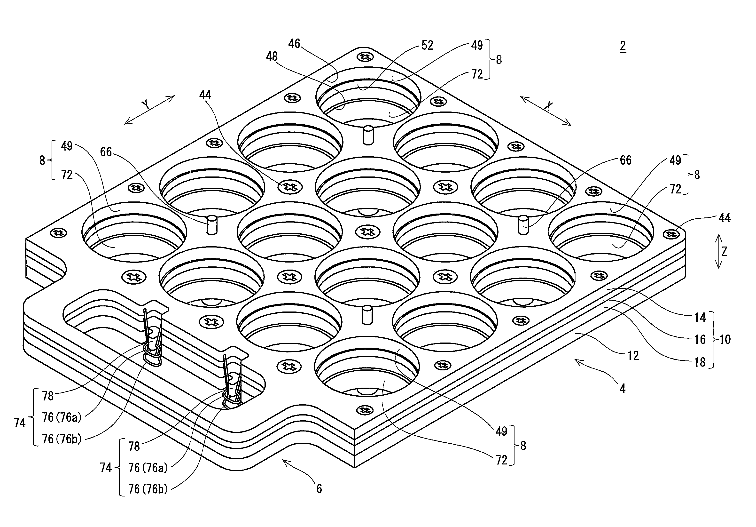
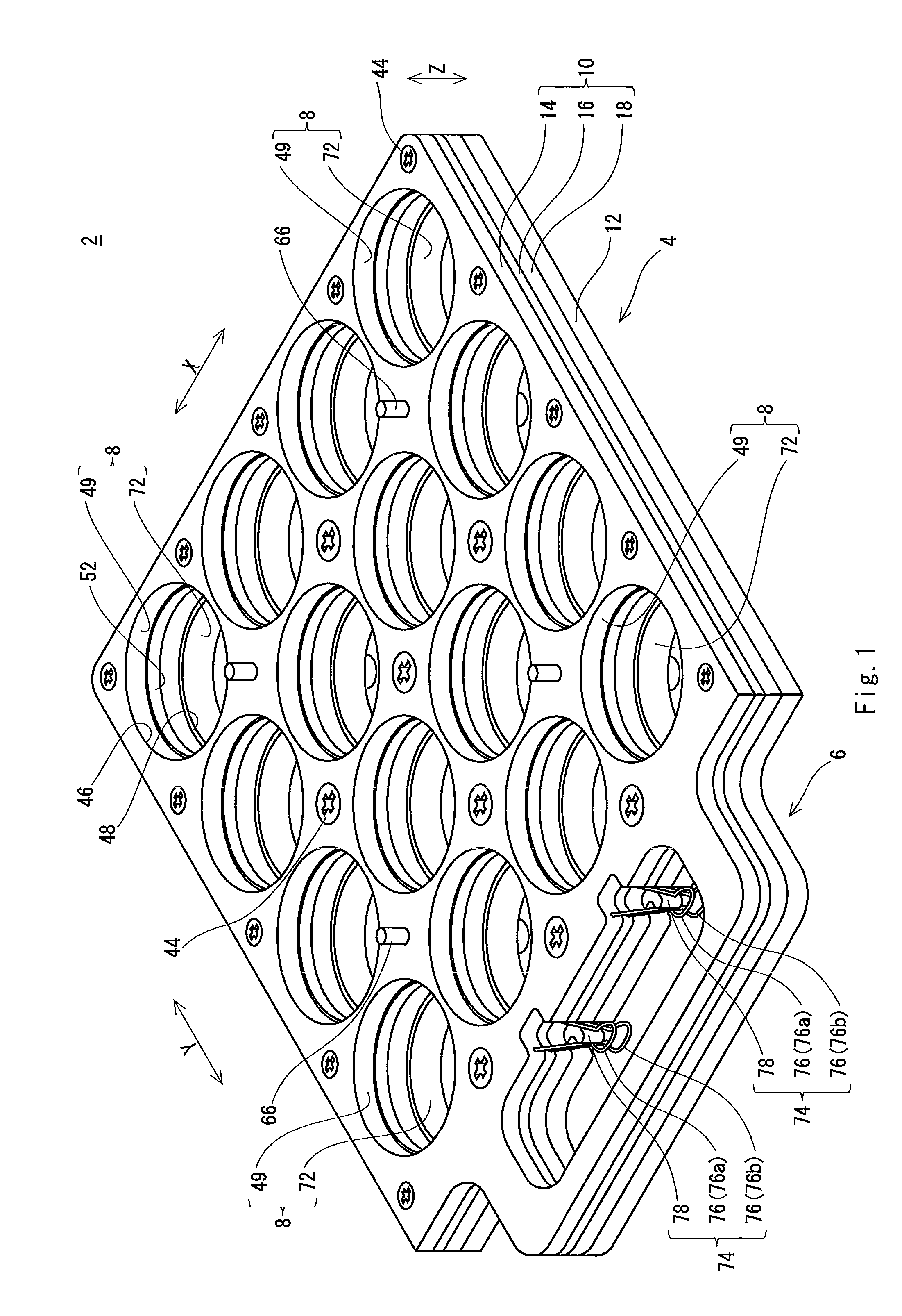
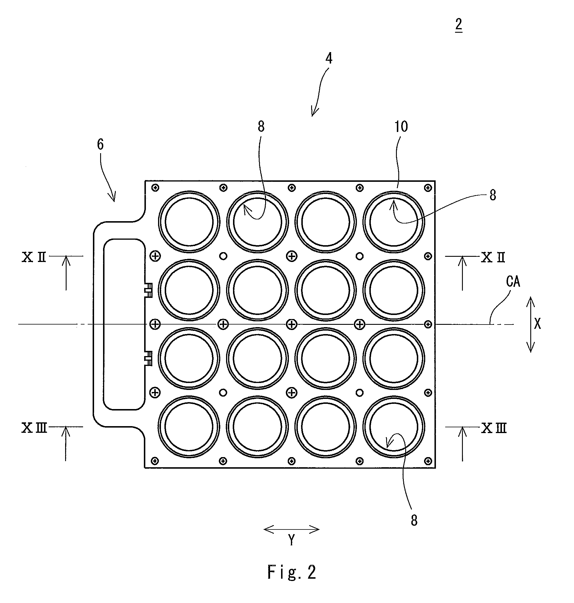
[0040]A tray 2, for an ink jet printer, shown in FIGS. 1 to 3 has a plate shape. Although not shown in the drawings, a golf ball on which a mark is to be printed by using the ink jet printer is to be set into the tray 2. An alternate long and short dash line CA represents the center line of the tray 2 in an X direction. A Z direction is the thickness direction of the tray 2.

[0041]The tray 2 includes a main body 4 and a grip 6. The main body 4 includes a plurality of cells 8. As shown in the drawings, the tray 2 is provided with 16 cells 8. The cells 8 are arranged in the tray 2 in a grid pattern. In the tray 2, four cells 8 are arranged in each line and at regular intervals in the X direction, and four cells 8 are arranged in each line and at regular intervals in a Y direction. Each of the cells 8 is made of a hole that extends through the tray...


PUM


Abstract

A tray 2 includes a holder 10 into which a golf ball is to be set. The holder 10 has: in an upper surface thereof and a lower surface thereof, openings 46 and 48 from which parts of the golf ball are exposed, respectively; and a contact portion 52 that comes into contact with the golf ball to fix in place the golf ball. The holder 10 is invertible. Preferably, the tray 2 further includes a base plate 12 on which the holder 10 is mounted. The base plate 12 has a stopper 72 that comes into contact with the golf ball set into the holder 10. The golf ball is fixed to the holder 10 such that the position of the center of the golf ball is caused to agree with the position of the center of the holder 10 in a thickness direction thereof due to this contact.

Description

[0001]This application claims priority on Patent Application No. 2009-8698 filed in JAPAN on Jan. 19, 2009. The entire contents of this Japanese Patent Application are hereby incorporated by reference.BACKGROUND OF THE INVENTION[0002]1. Field of the Invention[0003]The present invention relates to trays for an ink jet printer and methods of manufacturing a golf ball having a mark.[0004]2. Description of the Related Art[0005]A golf ball manufacturer prints a mark on the surface of a golf ball and ships the golf ball. The mark includes characters, graphics, combinations of characters and graphics, and the like. Typically, the trademark of the golf ball is printed. The mark representing the trademark is referred to as a main mark. A user recognizes the type of the golf ball by identifying the main mark. In some cases, a mark corresponding to the user is also printed on the golf ball. The mark is referred to as an own name mark. Specific examples of the own name mark include the name of ...

Claims


Application Information

Patent Timeline
IPC IPC(8): B41J29/38B65D1/34
CPCA63B37/0003A63B45/02B41J3/4073B41J11/02A63B37/0022B41J3/40731
Inventor MATSUI, NORIYUKIAMASAKI, MASAAKI
Owner SUMITOMO RUBBER IND LTD
Learn More