Carriage bottom plate drilling locator

A technology of a compartment floor and a locator, which is applied to the measurement of positioning in the boring machine/drilling machine, drilling/drilling equipment, workshop equipment, etc., can solve the problems of increasing the labor intensity of workers, affecting the service life of vehicles, and reducing work efficiency. , to improve work efficiency and maintenance quality, reduce labor intensity and maintenance costs, and eliminate potential safety hazards.

Active Publication Date: 2014-10-15
MAGANG (GROUP) HOLDING CO LTD +1
View PDF5 Cites 8 Cited by
  • Summary
  • Abstract
  • Description
  • Claims
  • Application Information

AI Technical Summary

Problems solved by technology

Its defect is that the use of wooden strips requires special personnel to measure and mark them. Once the wooden strips are stored for a long time, the left and right marks will be wrongly marked due to the memory error of the special personnel. It needs to be measured and marked again, which is time-consuming and laborious. When the beam is used, it will be deformed to different degrees, coupled with the error of the wooden strip mark and the transfer of the marking reference, resulting in a large misalignment error between the rivet holes of the bottom plate and the rivet holes of the bottom beam, making subsequent drilling and reaming very difficult, and the deviation When the welder cuts the hole again, the drill bit and reamer may be broken, which not only increases the labor intensity of the workers and reduces the work efficiency, but also poses a serious safety hazard. The quality of riveting decreases, which affects the service life of the vehicle

Method used


Image

  • Carriage bottom plate drilling locator
  • Carriage bottom plate drilling locator

Examples


Embodiment Construction

[0017] The present invention will be further described below in conjunction with embodiments.

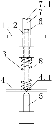
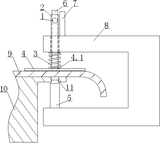
[0018] by figure 1 , 2 It can be seen that the carriage floor drilling locator is composed of a bow-shaped bracket 8, a positioning pin 5, and a punching mechanism. The upper wing of the bow-shaped bracket is provided with a punching mechanism with a sample punch 6, and the lower wing of the bow-shaped bracket sets position pins. The center axis of the punch and the center axis of the positioning pin are on the same vertical line.

[0019] The arch-shaped bracket 8 is an open rectangular frame. The upper wing and the lower wing are parallel and in the same vertical plane. The distance between the two wings of the rectangular frame is greater than the sum of the thickness of the upper wing of the bottom beam 10 and the bottom plate 9; the width of the rectangular frame is adapted to the front end of the bottom plate. The wing is provided with a through hole, a limit baffle 7 is provided n...


PUM


Abstract

The invention relates to a carriage bottom plate drilling locator, belongs to machining auxiliary equipment and in particular relates to a drilling locating device. The carriage bottom plate drilling locator is characterized in that the locator consists of an arch-shaped support, a locating pin and an anvil engraving mechanism in a connecting way, the anvil engraving mechanism with an anvil is arranged on an upper wing of the arch-shaped support, the locating pin is arranged on a lower wing of the arch-shaped support, and the central axis of an anvil head and the central axis of the locating pin are on the same plumb line. The carriage bottom plate drilling locator has the advantages that the concept is novel and the structure is simple, compact and reasonable; by using the drilling locator, multi-person and multi-process operations such as processing a wood strip, measuring hole distance on the wood strip, extending and snapping the line, measuring hole distance by using the wood strip and punching anvil holes one by one can be omitted, the operation is simple and convenient, rivet hole anvil holes can be easily, accurately and inerrably punched side beam bottom plates on two sides by one person in one step, each hole takes a corresponding bottom beam rivet hole as a datum, errors caused by datum transformation are avoided, the bottom plate rivet hole marking accuracy is greatly improved, the labor intensity of workers and the repair costs are reduced, the working efficiency and the repair quality are improved, the safety and the reliability are high and the potential safety hazards are eliminated.

Description

Technical field [0001] The invention belongs to mechanical processing auxiliary equipment, and particularly relates to a drilling positioning device. Background technique [0002] After the railway self-overturning wagon has been used for a period of time, due to the damage and waste of the carriage floor, it is necessary to remove the floor, and then lay a new floor. The new floor is drilled to match the rivet holes of the bottom beam and riveted together by rivets. Since the bottom beam of the carriage is composed of I-steel and channel steel, and there will be a large downward axial force during drilling, the drilling machine cannot drill the nail holes of the bottom plate from the direction of the bottom beam of the carriage, only from above the newly laid bottom plate For drilling, it is necessary to drill a rivet hole completely concentric with the bottom beam rivet hole on the bottom plate, so that the rivet can be smoothly penetrated for riveting. It is very difficult to ...

Claims


Application Information

Patent Timeline
Patent Type & Authority Applications(China)
IPC IPC(8): B23B49/00B25H7/04
CPCB25D5/00
Inventor 马守斌张桂娟
Owner MAGANG (GROUP) HOLDING CO LTD
Why Eureka
Try Eureka