Reception device, transmission device, and adaptive transmission rate control method
a transmission device and transmission technology, applied in the field of adaptive transmission rate control, can solve problems such as inaccurate transmission and not necessarily tru
- Summary
- Abstract
- Description
- Claims
- Application Information
AI Technical Summary
Benefits of technology
Problems solved by technology
Method used
Image

Examples
embodiment 1
[0131]The following is an explanation of Embodiment 1 in the present invention, with reference to the attached drawings. Note that in Embodiments 1 and 2, the modulation method, coding rate, number of transmission streams, bandwidth, and guard interval length are listed as factors for adaptively controlling the transmission rate, but factors can be chosen freely. For example, only the modulation method and coding rate may be used.
[0132]
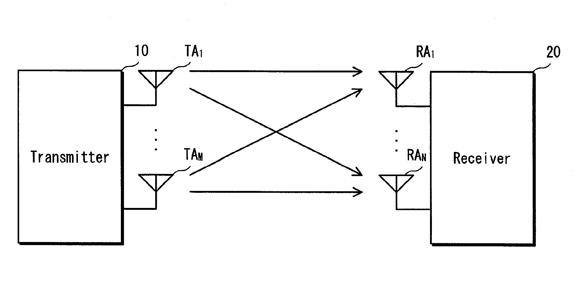
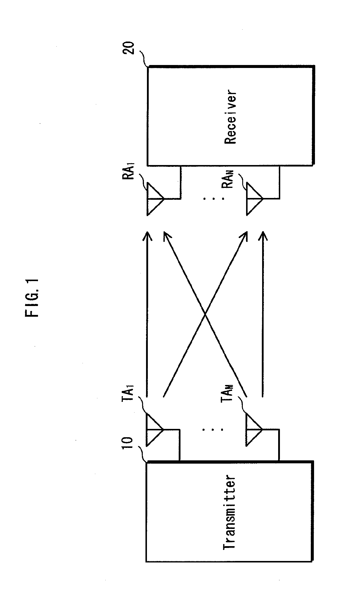
[0133]The MIMO transmission system in the present embodiment is now explained with reference to FIG. 1, which is a system configuration diagram of the MIMO transmission system in the present embodiment.
[0134]The MIMO transmission system shown in FIG. 1 includes a transmitter 10 provided with M antennas TA1-TAM (M being an integer equal to or greater than two) and a receiver 20 provided with N antennas RA1-RAN (N being an integer equal to or greater than two). Note that, normally, the receiver 20 provided with N antennas RAd-RAN is capable of performin...
embodiment 2
[0205]The following is an explanation of Embodiment 2 of the present invention, with reference to the attached drawings.
[0206]In Embodiment 1, the adaptive control unit 211 used the received signal strength as is to determine the transmission rate with reference to the strength rate information. In the present embodiment, however, the adaptive control unit 211a corrects the received signal strength based on the likelihood correction value and determines the transmission rate using the corrected value for the received signal strength with reference to the strength rate information. Note that since the structure and operations of the adaptive control unit 211a differ essentially from Embodiment 1, explanation is provided for the adaptive control unit 211a in the present embodiment.
[0207](Structure of Adaptive Control Unit 211a)
[0208]The following is an explanation of the adaptive control unit 211a in the present embodiment with reference to FIG. 9, which is a block diagram of the adap...
embodiment 3
[0218]The following is an explanation of Embodiment 3 of the present invention, with reference to the attached drawings.
[0219]The adaptive control unit 211b in Embodiment 3 performs different adaptive control processing than the adaptive control processing performed by the adaptive control unit 211 in Embodiment 1. In the present embodiment, the elements of the transmission rate of which the receiver 20b notifies the transmitter 10 are the modulation method and the coding rate, and therefore the adaptive control unit 101 in the transmitter 10 sets the coding rate in the coding unit 104 and the modulation method in the modulators 1061-106M in accordance with the notification from the receiver 20b, setting other elements to predetermined values. Note that since the structure and operations of the receiver 20b differ essentially from Embodiment 1, explanation is provided for the receiver 20b in the present embodiment.
[0220]20b>
[0221]The following is an explanation of the receiver 20...
PUM
 Abstract
Description
Claims
Application Information