Heat-generating element of a heating device

a heating device and heat-generating element technology, applied in the direction of resistors, non-adjustable resistors, air heaters, etc., can solve the problems of disturbance of the self-regulation characteristics of ptc elements, local overheating, and damage to heat-generating elements, so as to increase the safety and increase the safety

Inactive Publication Date: 2010-02-23
CATEM
View PDF37 Cites 17 Cited by
  • Summary
  • Abstract
  • Description
  • Claims
  • Application Information

AI Technical Summary

Benefits of technology

[0010]The object of the invention under consideration is to provide a heat-generating element of a heating device for heating air, as well as a corresponding heating device, offering increased safety. At the same time, the invention under consideration particularly seeks to increase the safety with regard to a possible electric flashover.

Problems solved by technology

Otherwise, the problem that arises is an increased transition resistance, which, particularly in the case of the use of heat-generating elements in auxiliary heaters for motor vehicles, can lead to local overheating due to the high currents.
As a result of this thermal event, the heat-generating element can be damaged.
Furthermore, the PTC elements are self-regulating resistance heaters that emit a lower heat output at an increased temperature, so that local overheating can lead to a disturbance in the self-regulating characteristics of the PTC elements.
In addition, at the high temperatures in the area of an auxiliary heater, vapours or gases can develop that can result in a direct hazard for persons in the passenger compartment.
Correspondingly problematic is also the use of generic heat-generating elements at high operating voltages, such as voltages up to 500 V, for example.
For one thing, a problem here is that the air that flows against the heat-emitting elements carries moisture and / or dirt with it, which can penetrate into the heating device and cause an electric flashover, i.e., a short-circuit, here.
On the other hand, there is fundamentally the problem of protecting persons working in the area of the heating device from the current-carrying parts of the heating device or of the heat-generating element.
It has been seen, however, that in generic heat-generating elements when high voltages are used, an electric flashover cannot always be avoided, due to a low resistance to leakage current.

Method used


Image

  • Heat-generating element of a heating device
  • Heat-generating element of a heating device
  • Heat-generating element of a heating device

Examples


Embodiment Construction

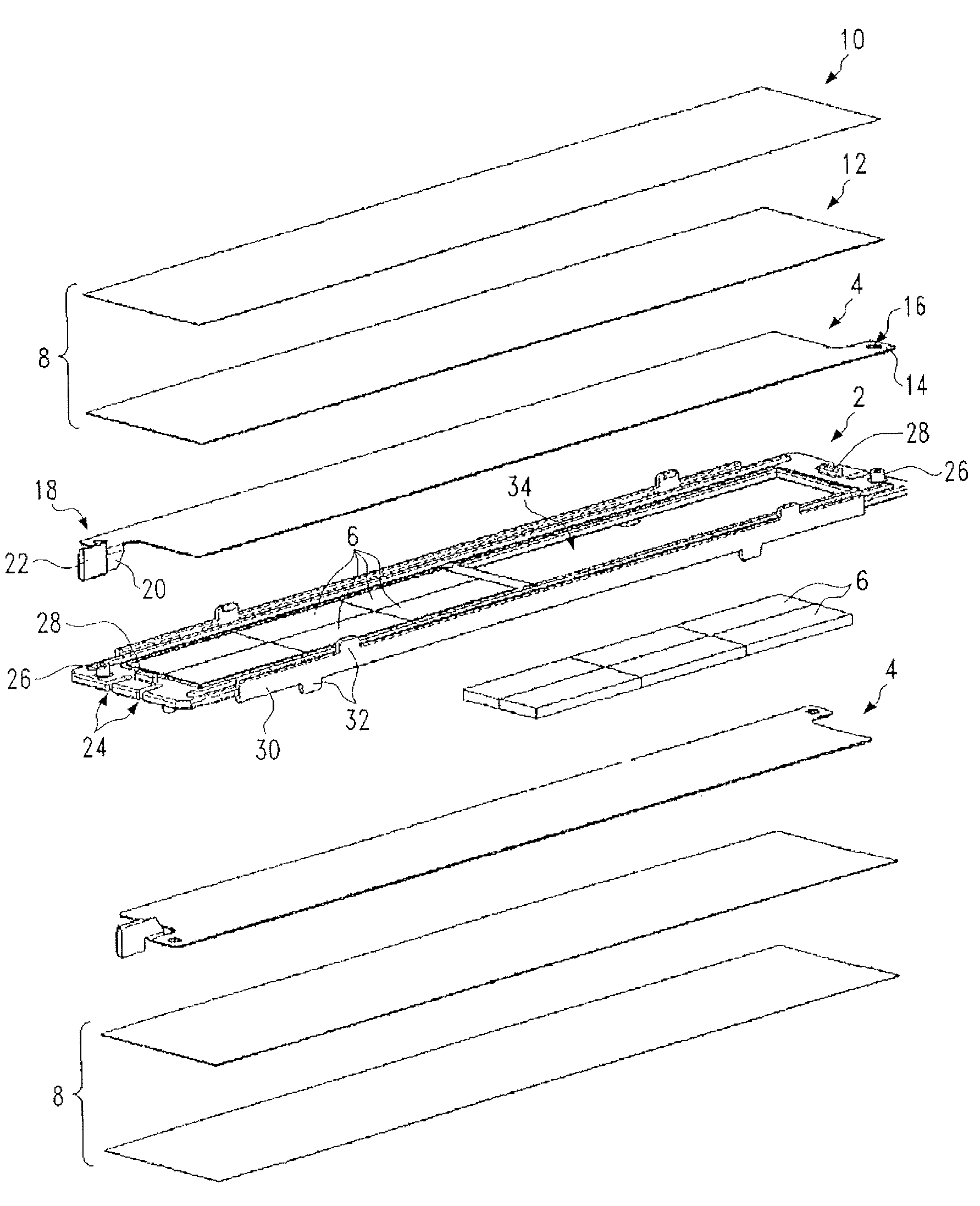
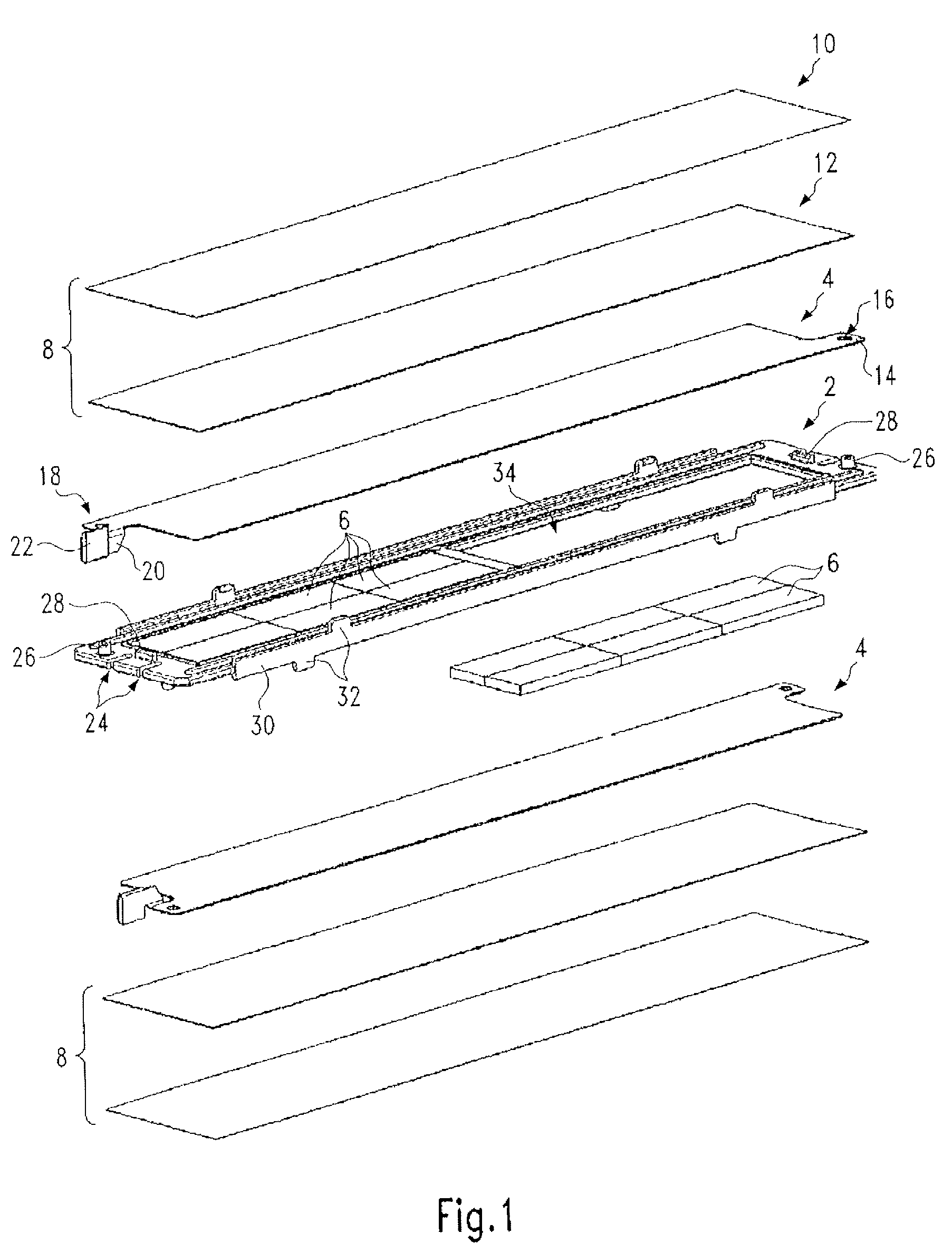
[0052]FIG. 1 shows a perspective side-view of the essential parts of an embodiment of a heat-generating element in a blown-up representation. The heat-generating element has a positioning frame 2, made of injection-moulded plastic, whose middle longitudinal axis forms a bisecting plane of the heat-generating element. This element is essentially formed with one side the mirror image of the other, and initially has contact plates 4 provided on each side of the positioning frame 2, said contact plates holding between them the PTC elements 6 held in the positioning frame 2. On the exterior side of the contact plates 4 is located a two-layer insulating layer 8, comprising an exterior insulating foil 10 and an inner ceramic plate 12, that fits directly against the contact plate 4. The ceramic plate 12 is a relatively thin aluminium oxide plate that provides very good electric dielectric strength of roughly 28 kV / mm and good thermal conductivity of more than 24 W / (m K). The plastic foil 10...


PUM


Abstract

A heat-generating element of a heating device for heating air includes at least one PTC element and, lying on opposing side surfaces of the PTC element, electric strip conductors. A heat-generating element that is improved with a view to safety from electric flashovers and leakage currents is created with the invention under consideration by providing an insulating gap between the PTC element and the positioning frame material that circumferentially surrounds the frame opening. Also disclosed is a heating device for heating air with multiple heat-generating elements, each heat-generating element comprising at least one PTC element and, lying on opposing side surfaces of the PTC element, electric strip conductors and multiple heat-emitting elements that are arranged in parallel layers and that are held in position in a frame on opposing sides of the heat-generating element with a spring bias. Due to the use of a heat-generating element, the heating device is protected from electric flashovers and leakage currents with a higher degree of certainty.

Description

BACKGROUND OF THE INVENTION[0001]1. Field of the Invention[0002]The invention under consideration relates to a heat-generating element of a heating device for heating air, comprising at least one PTC element and, lying on opposing side surfaces of the PTC element, electric strip conductors. Such a heat-generating element is known, for example, from EP 1 061 776, which is traced back to the current applicant.[0003]In particular, the heat-generating element is deployed in an auxiliary heater for a motor vehicle, and comprises multiple PTC elements, arranged in a row, one behind the other, that are energized via electric strip conductors that extend parallel to one another and that lie flat on opposing sides of the PTC elements. The strip conductors are normally formed by parallel strips of metal. The heat-generating elements formed in this way are deployed in a heating device for heating air in a motor vehicle, where said heating device comprises multiple layers of heat-generating ele...

Claims


Application Information

Patent Timeline
Patent Type & Authority Patents(United States)
IPC IPC(8): H05B3/10
CPCF24H3/0405F24H3/0429F24H3/0435F24H3/0447F24H3/0464F24H3/0476F24H3/082F24H9/1872H05B3/50H05B2203/02H05B2203/023H05B3/14H05B3/16
Inventor ZEYEN, MICHAELWALZ, KURTNIEDERER, MICHAELBOHLENDER, FRANZ
Owner CATEM
Why Eureka
Try Eureka