
Radio Base Station and Radio Communication Method

a radio communication and base station technology, applied in the direction of electrical equipment, wireless communication, etc., can solve the problems of insufficient prevention of reduction of the number of radio communication terminals currently connected to the radio base station, etc., to achieve the effect of reliably preventing deterioration of communication capability

Inactive Publication Date: 2010-07-22
KYOCERA CORP
View PDF3 Cites 17 Cited by
  • Summary
  • Abstract
  • Description
  • Claims
  • Application Information

AI Technical Summary

Benefits of technology

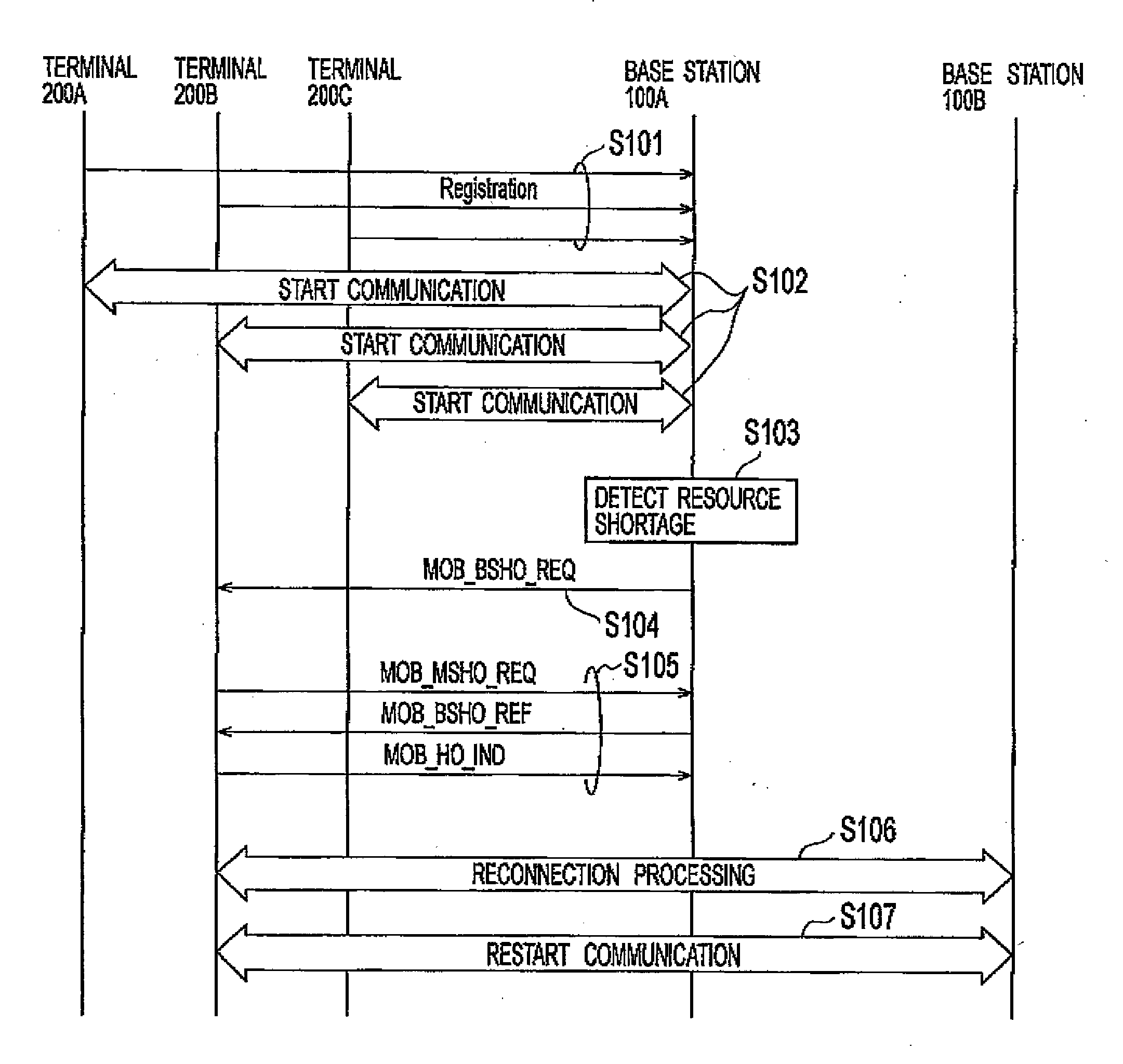
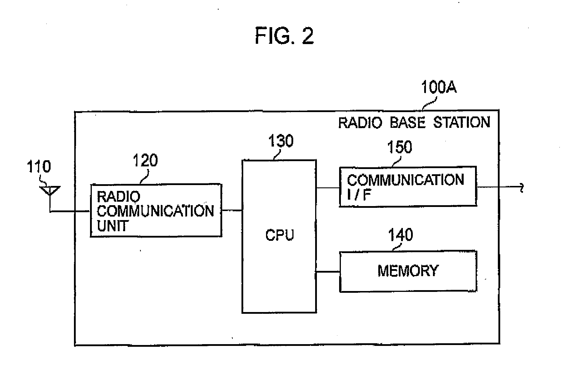
[0006]The present invention has been made in view of the above problem, and an object thereof is to provide a radio base station and a radio communication method which are capable of more reliably preventing a deterioration of the communication capability caused when the usage rate of a hardware resource of a radio base station reaches its limit value. To accomplish the object above, a first characteristic of the present invention is summarized as a radio base station (radio base station 100A) that communicates with radio communication terminals (radio communication terminal 200A, radio communication terminal 200B, and radio communication terminal 200C), and the radio base station includes: an acquiring unit (task manager 131) configured to acquire communication capability information while the radio base station is connected to the radio communication terminals, the communication capability information indicating a capability to communicate with the radio communication terminals (processing capability of CPU 130, for example); a judging unit (load judging unit 132) configured to judge whether or not the communication capability information acquired by the acquiring unit falls below a threshold; and a transmitter (packet generator 134 and communication processor 135) configured to transmit a switching request to at least one of the radio communication terminals (radio communication terminal 200B) if the judging unit judges that the communication capability information falls below the threshold, the switching request (MOB_BSHO_REQ message) requesting switching of a connection destination to a different radio base station (radio base station 100B).
[0008]Accordingly, when the usage rate of a hardware resource of the radio base station reaches a limit value and thus the communication capability is deteriorated to the threshold, the radio base station reduces the number of radio communication terminals currently connected thereto. Consequently, it is possible to more reliably prevent a deterioration of the communication capability caused when the usage rate of the hardware resource of the radio base station reaches a limit value.
[0016]According to the present invention, it is possible to provide a radio base station and a radio communication method which are capable of more reliably preventing a deterioration of the communication capability caused when the usage rate of a hardware resource of the radio base station reaches a limit value.

Problems solved by technology

For this reason, it is impossible to sufficiently prevent a deterioration of the communication capability caused when the usage rate of the hardware resource of the radio base station reaches the limit value.
Accordingly, when the usage rate of a hardware resource of the radio base station reaches a limit value and thus the communication capability is deteriorated to the threshold, the radio base station reduces the number of radio communication terminals currently connected thereto.

Method used


Image

  • Radio Base Station and Radio Communication Method
  • Radio Base Station and Radio Communication Method
  • Radio Base Station and Radio Communication Method

Examples


first embodiment

(1) Schematic Configuration of Radio Communication System

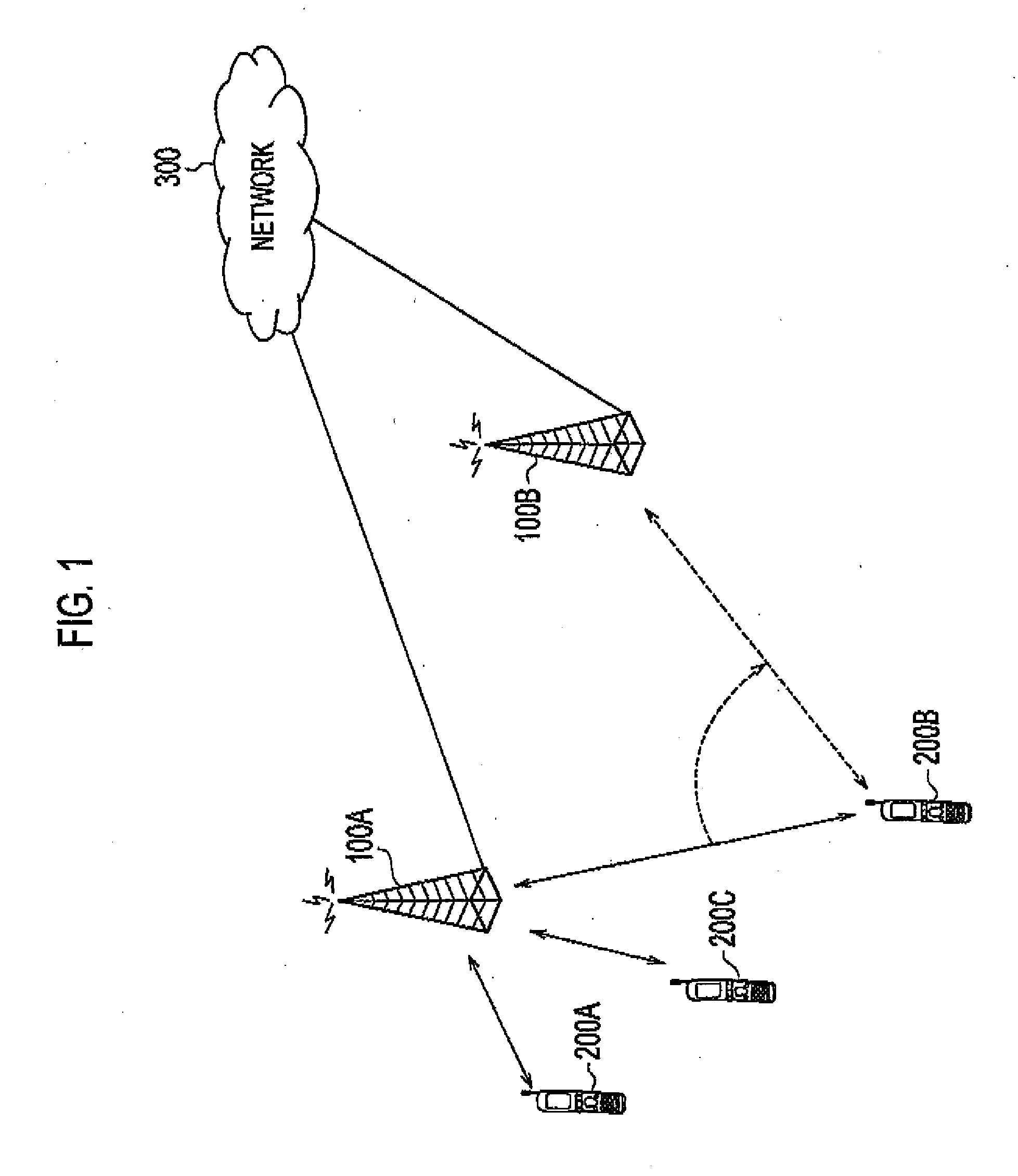
[0031]To begin with, a schematic configuration of a radio communication system according to this embodiment will be described. FIG. 1 is a schematic configuration diagram of the radio communication system according to this embodiment. In this embodiment, the description will be given for a radio communication system based on mobile WiMAX (IEEE802.16e-2005 standard).

[0032]As shown in FIG. 1, the radio communication system according in to this embodiment includes a radio base station 100A, a radio base station 100B, a radio communication terminal 200A, a radio communication terminal 200B, and a radio communication terminal 200C. The radio base station 100A and the radio base station 100E are connected to a network (IF network) 300.

[0033]Each of the radio communication terminal 200A, the radio communication terminal 200B, and the radio communication terminal 200C has established a connection to the radio base station 100A, and is...

second embodiment

[0077]In this embodiment, differences from the above-described first embodiment will be mainly described, and overlapping descriptions will be omitted.

(1) Schematic Configuration of Radio Communication System

[0078]FIG. 6 is a schematic configuration diagram of a radio communication system according to this embodiment. As shown in FIG. 6, the radio communication system according to this embodiment is different from FIG. 1 in that it includes a terminal is management server 400 connected to the network 300.

[0079]The terminal management server 400 manages information on radio communication terminals (radio communication terminal 200A, radio communication terminal 200B, and radio communication terminal 200C) currently connected to radio base stations (radio base station 100A and radio base station 100B).

[0080]In this embodiment, the terminal management server 400 receives information on the radio communication terminal 200A, the radio communication terminal 200B, and the radio communica...


PUM


Abstract

A radio base station according the present invention communicates with a radio communication terminal which has established a connection. The radio base station includes: a task manager 131 configured to acquire communication capability information indicating processing capability of CPU; a load judging unit 132 configured to judge whether or not the communication capability information falls below a threshold; and a packet generator 134 and a communication processor 135 configured to transmit MOB_BSHO_REQ message requesting switching of a connection destination to a different radio base station to at least one of the radio communication terminals if judged that the communication capability information falls below the threshold.

Description

TECHNICAL FIELD[0001]The present invention relates to a radio base station and a radio communication method for communicating with a radio communication terminal which has established a connection.BACKGROUND ART[0002]Generally, in a radio communication system, a radio communication terminal on the move performs a handover to switch its connection destination to a radio base station having a better condition. Specifically, a radio communication terminal makes a comparison of the received powers of broadcast signals broadcasted by multiple radio base stations, and then switches its connection destination to a radio base station from which the highest received power is obtained.[0003]In such a radio communication system, a large number of radio communication terminals located around one radio base station may connect to the radio base station at the same time. In this case, the usage rate of a hardware resource, such as a MY or a memory, provided to the radio base station reaches its l...

Claims


Application Information

Patent Timeline
IPC IPC(8): H04W36/34H04W36/22
CPCH04W36/22H04W36/38
Inventor TACHIKAWA, HITOYA
Owner KYOCERA CORP
Learn More