Intelligent cache injection

a cache and intelligent technology, applied in the computer field, can solve the problems of limited space within the cache, fraught injection process, and problems

Active Publication Date: 2010-07-22
DAEDALUS BLUE LLC
View PDF1 Cites 7 Cited by
  • Summary
  • Abstract
  • Description
  • Claims
  • Application Information

AI Technical Summary

Problems solved by technology

Because the amount of room within a cache is limited, a cache / memory controller will only store in cache the instructions / data that are needed by the processor.
However, the injection process is fraught with problems and issues, particularly in deciding which cache will be the candidate for injection of an evicted cache line.

Method used


Image

  • Intelligent cache injection
  • Intelligent cache injection
  • Intelligent cache injection

Examples


Embodiment Construction

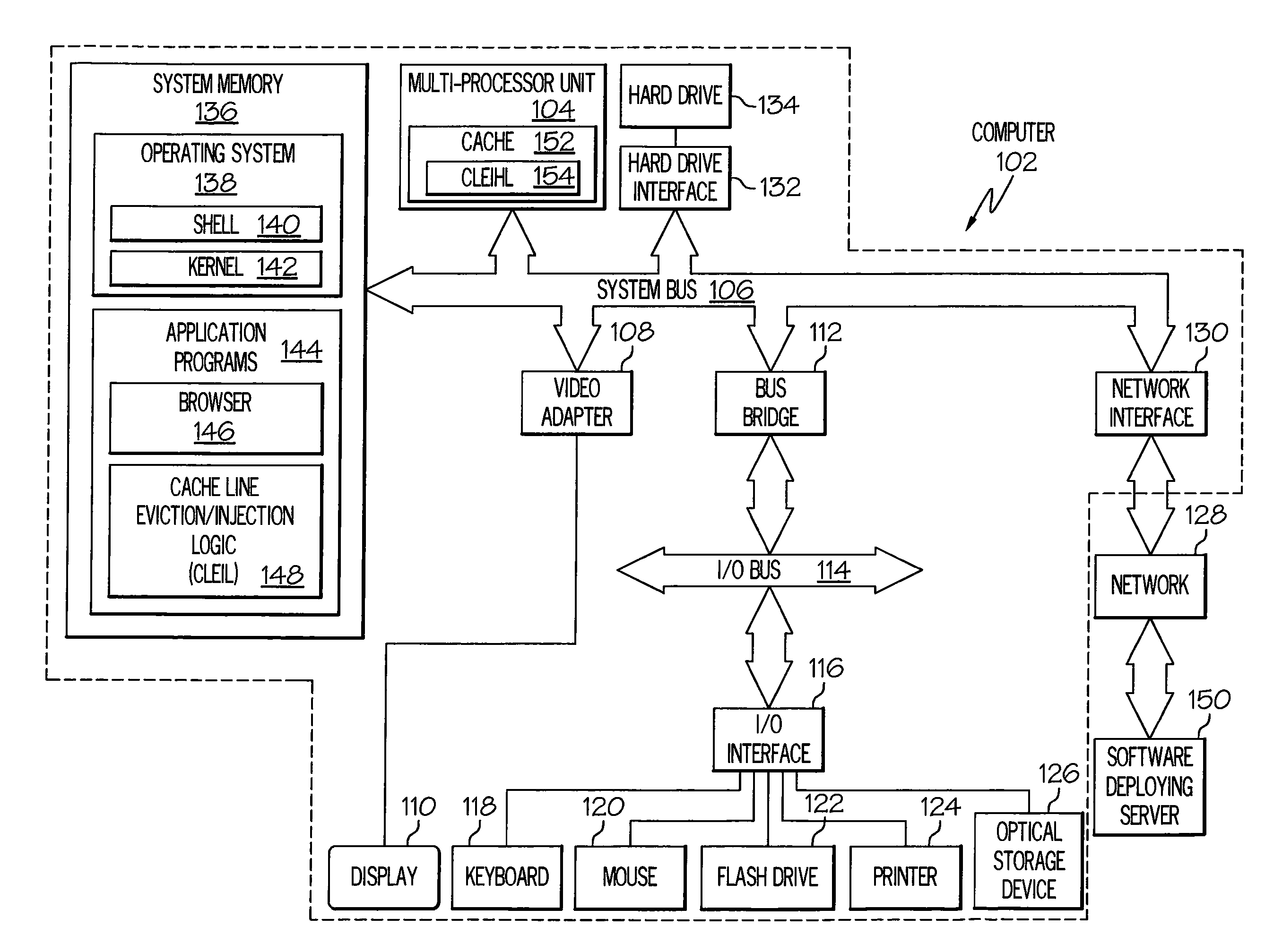
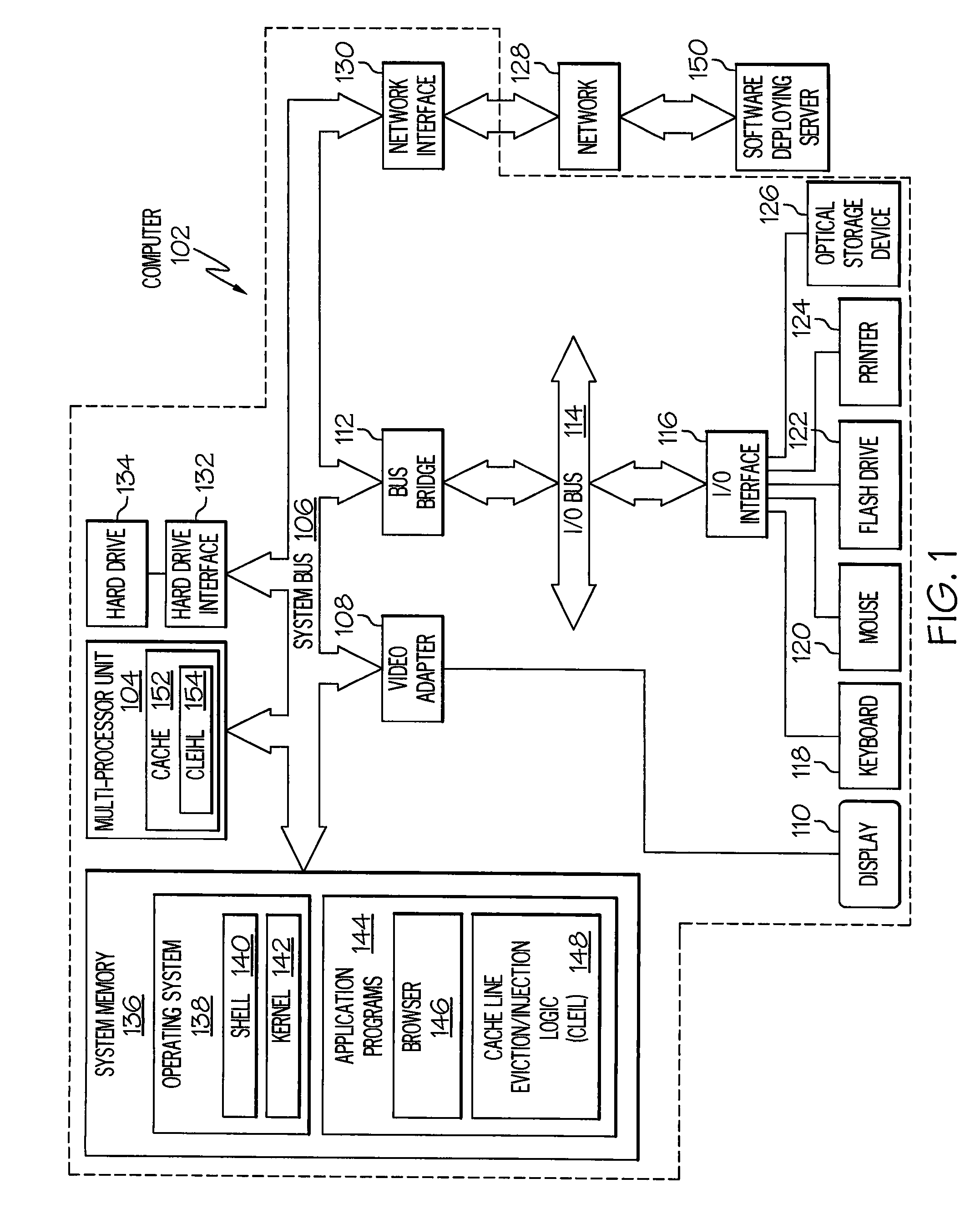
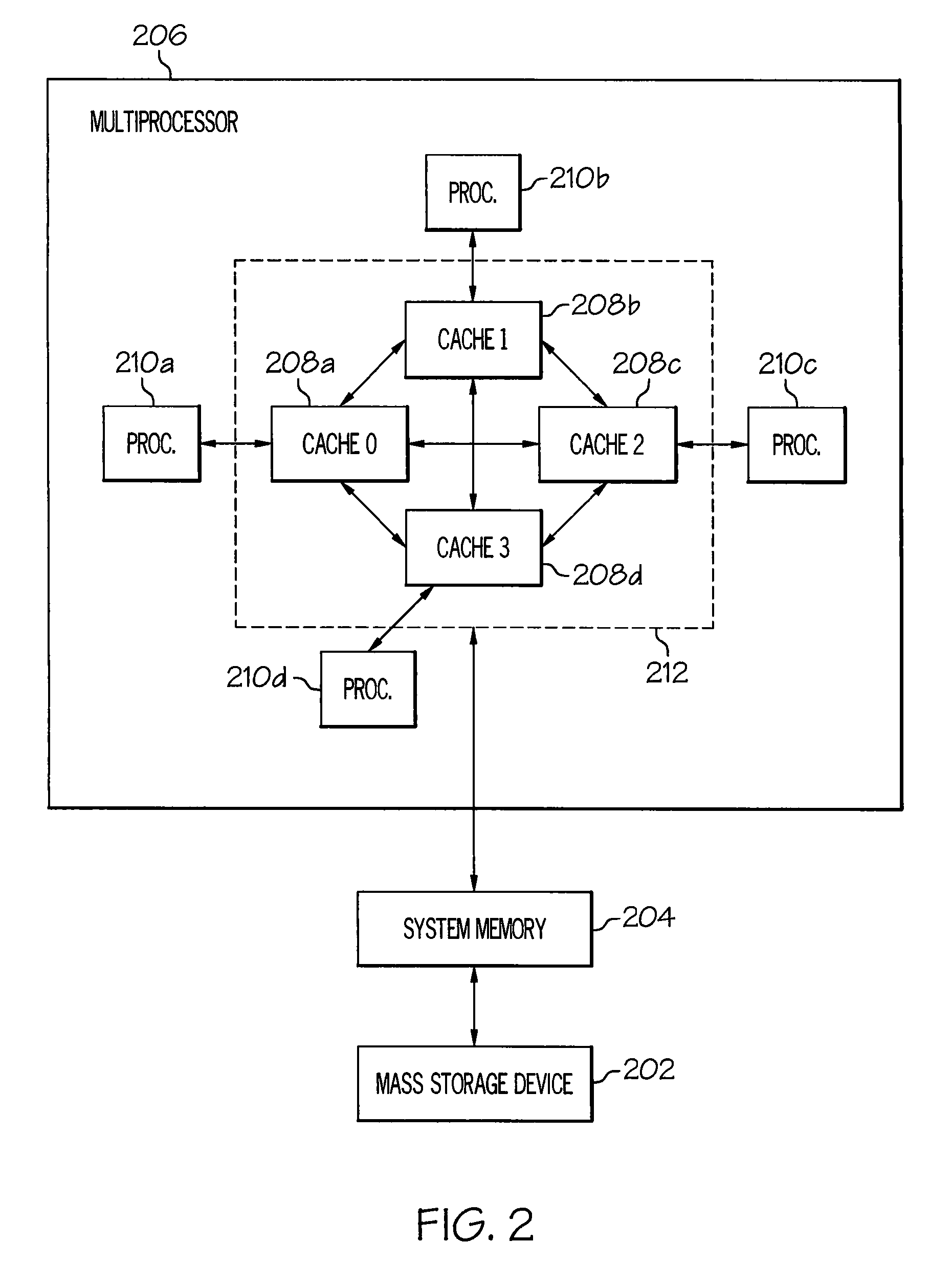
[0017]In a multi-processor computer system in which each processor employs one or more caches, it can be advantageous to move an evicted line from one cache to another. For example, if the processor associated with one cache is much busier than another processor, it may make sense to allow the busy processor to evict lines from its cache into the less busy processor's cache. If the evicted line is later needed by the same or even a different processor, it can more quickly be retrieved from the remote cache than from Dynamic Random Access Memory (DRAM), also known as “memory” or “system memory.” To distinguish between evicted lines that go to memory versus lines that pass to another cache, the latter case (pushing evicted lines to another cache) is referred to as “cache injection.”

[0018]There are multiple caches in which the line could be injected. Ideally, the line is placed in a cache that would not be perturbed by the addition of the evicted line. To accomplish this goal, the pres...


PUM


Abstract

A first cache simultaneously broadcasts, in a single message, a request for a cache line and a request to accept a future related evicted cache line to multiple other caches. Each of the multiple other caches evaluate their occupancy to derive an occupancy value that reflects their ability to accept the future related evicted cache line. In response to receiving a requested cache line, the first cache evicts the related evicted cache line to the cache with the highest occupancy value.

Description

BACKGROUND OF THE INVENTION[0001]1. Technical Field[0002]The present disclosure relates to the field of computers, and specifically to memory storage. Still more particularly, the present disclosure relates to managing cache data.[0003]2. Description of the Related Art[0004]Cache memory (cache) is defined as a local high-speed memory, which is typically located within or near a core of a processor. Because the amount of room within a cache is limited, a cache / memory controller will only store in cache the instructions / data that are needed by the processor. Thus, caches often replace (“evict”) less frequently used blocks of data (hereafter a “cache line” or just “line”) to make room for more recently used data. In most systems the line is either written back to memory (if the evicted line has been modified) or simply replaced by the newer line (if the evicted line has not been modified). Either action is known as “evicting” the line. After the line has been evicted, it may be again n...

Claims


Application Information

Patent Timeline
Patent Type & Authority Applications(United States)
IPC IPC(8): G06F12/08
CPCG06F12/128G06F12/0815
Inventor HEIL, TIMOTHY H.HOOVER, RUSSELL D.JOHNSON, CHARLES L.VANDERWIEL, STEVEN P.
Owner DAEDALUS BLUE LLC
Why Eureka
Try Eureka